 |

|
 |


Begin OCR Text:
B u _ p E _ _
,'__ _8
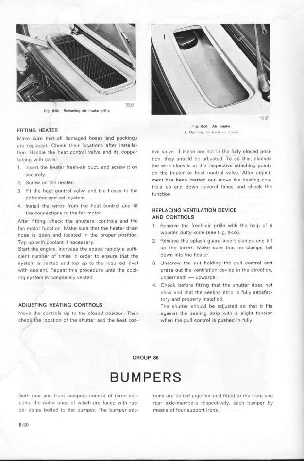
Fig. 0-55. Removing air intake grille vo_vu
Fig. 8-a. Air intake ''' _
FlnING HEATER _ o_,,.,,g F,, F,,,_.,,, ,,_,_,
Make sure that all damaged hoses and packingS
are replaced. Check their locations after installa-
e_on. Hand_e the heat control ualue and its copper trol valve. If these are not in the fully closed posi-
tub_ng wieh šare. tion, they should be adjusted. TO do thýs, SlaCken
_ . _ngerEUR ehe heater Fregh-a__r duše, and gšrew _e on the wire sleeves at the respective attaching points
gešure_y. on the heater or heat Contfol valve. Aftef adjust_
_ ment has been carried out moue the heating con-
2. CreW On the heatef. '
trols up and down several times and check the
3 F_t the heaf šontrol valve and the hoses to the
' function.
defroster and cell system.
q _nsta_l the wires from the heat control and fit _
' REPLACING VENTILATlON DEVICE
the COnneCtlOnS tO the fan mOtOr. AND CONTROLS
After fitting. chech the shutterS, controls and the
Fan moEURor FunšEUR_on Make gure ehae ehe heaeer dra_n 1 . Remove the fresh-air grille with the help of a
hoge _g open and' _ošaeed ._n the proper pog.ie._on. wooden putty knife (see fig. 8_55).
Top ,p w_th šoo_ane _F nešeggary. 2. Remove the splash guard insert clamps and lift
_eare ehe eng_ne. _nšreage EURhe gpeed rap_,d_y a guFF_- up the insert. Make sure that no clamps fall
šienEUR number oF tjmeg _n order eo engure ehat ehe doWn into the heater.
system is vented and top up to the requ_red level 3. Unscrew the nut holding the puII control and
with coolant. Repeat this procedure until the cool- press out the ventilation deu_ce in the direction.
ing system is completely vented. underneath - upwards.
4. Check before fitting that the shutter does not
st_ck and that the sealing strip is fully satisfac-
tory and properly installed.
ADlUSTING HEATING CONTROLS The ghueeer ghou_d be ad)usted so that it fjts
Move the controls up to the closed position. Then against the seaIing strip with a slight tension
check the location of the shutter and the heat con- when the pull control is pushed in fuIIy.
GROUP 86
Both I_ear and front bumpers consist of three sec- tions are bolted together and (itted to the front and
iionc_, the oute-_ ones of wh_ch are faced with rub- rear side-members respectively, each bumper by
ber _tr1ps bolted to the bumper. The bumper sec- means of four support irons.
8_.2O
|

