 |

|
 |


Begin OCR Text:
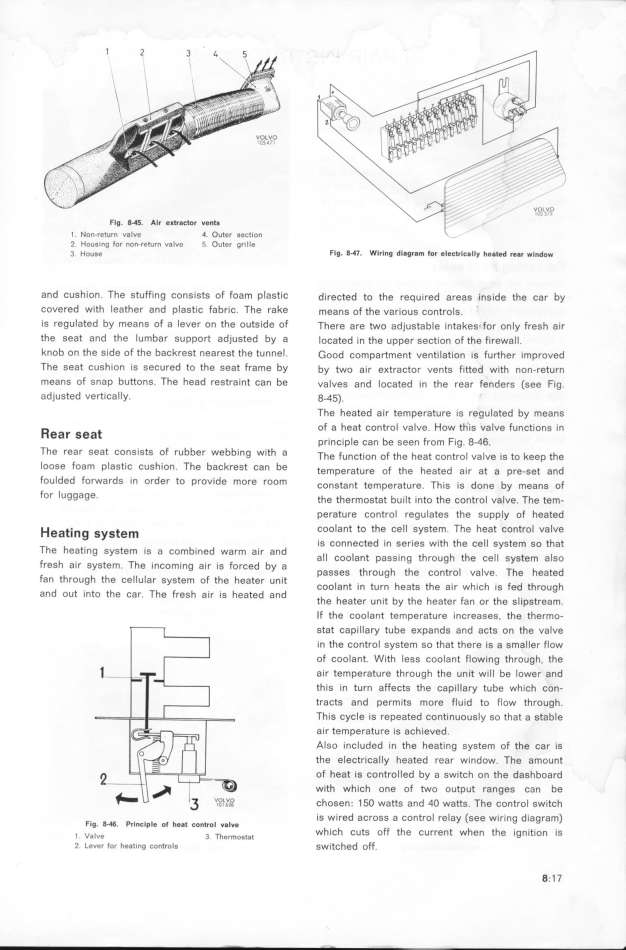
FIg. B_. AIr e__a_tor ve_t_
_ _o___e_u__ va_ve 4. Outer section _ -
2 HouGing for non_return v8lve 5 Outer grille
3 HDu6e Flg. P47_ WlrIng diagr6m for ele_trically heated rear _lndo_
and cushion. The stuffing consists of foam plastiC directed to the required areas inside the car by
covered with Ieather and plastic fabric. The rake mea,g of the various controls. '
is reguIated by means of a lever on the outside of There are two adjustable intakes_ for only fresh air
the seat and the lumbar support adjusted by a located in the upper section of the firewall.
knob on the side of the backreSt nearest the tunneI. _ood compartment ventilation is further improved
The seat cushion is secured to the Seat frame by by two air e_tractor vents fitted with non-return
means of snap buttonS. The head feStraint can be valves and located in the rear fenders (see Fig.
adjusted vertically. 8-45).
The heated air temperature is regulated by means
_ _ of a heat control valve. How th'is valve functions in
eaf Sea _ _ _ b F F_ g q6
princip e Can e Seen fOm Ig. - .
The fear Seat ConSiStS Of rUbber Webbin9 With a ihe Fu,ct_o, oF the heat contro_ va_ve is to keep the
IooSe foam plaStiC CuShion. The baCkreSt Can be temperature oF the heated a_r at a pre_get a,d
foUlded fofwards in order to provide mofe room ,o,gta,t temperat,re. Thig _g do,e by mea,g of
for lug9age_ the thermostat bu__t _nto the controI valve. The tem-
perature control regulates the supply of heated
H __ _ coolant to the Cell SyStem. The heat COntfol VaIVe
ea l_9 SyS ern is connected in series with the cell system so that
The heating system is a combined warm air and h h h __ _
all coolant paSsing t roug t e ce system a so
ffeSh aif SyStem The inComing air iS forCed by a h h h t _ _ ih h t d
_ passes t roug t e Con fo va ve. e ea e
fan through the ceIluIar system of the heater unit h h F d h h
coolant in turn heats t e air w ich is e t roug
and out into the car The fresh air is heated and h F h _
' the heater unit by the eater an or t e s ipstream.
If the coolant temperature increases, the thermo-
stat capillary tube e_pands and acts on the valve
in the control system so that there is a smaller flow
of coolant. With less coolant flowing through, the
air temperature through the unit wiIl be lower and
this in turn affects the capillary tube which con-
tracts and permits more fluid to fIow through.
This cycle is repeated continuously so that a stable
air temperature is achieved.
Also included in the heating system of the car iS
the electricaIIy heated rear window. The amount
of heat is controlled by a switch on the dashboard
with which one of two output ranges can be
chosen. 1 5O watts and 4O watts. The control switch
is wired across a control relay (see wiring diagram)
FIg. 0_46. Princlple of he8t cDntrol valve h
which cuts off the current when t e ignition is
l Valve 3. Thermostat
_ Leuer for heating con_ro_s switched off. 8; 1 7
|

