 |

|
 |


Begin OCR Text:
_ _
4. Adjust the location of the steering bo_ so that
the least possible tension is obtained in the
clutch disc. Tighten the aftaching bolts. Tighten
the nut on the tensioning sleeve to a torque of
_5 kpm (22-36 lb.ft.) and lock it with punch
pops on the sIit of the tensioning sleeve, see
fig. 6-46.
Connect the horn cable.
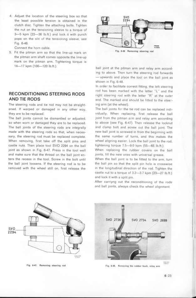
5 F.t th .t th h _ k Flg. 6_ Removlng steeri_g rDd
. l e pl man arm SO at t e Ine-Up mar on
the pitman arm shaft comes opposite the line-up
mark on the pitman arm. Tightening torque is
1 4-1 7 kpm (1 O_1 2O Ib ft ) b __
' ' ' a jOlnt at the pItman afm and felay arm aCCord-
ing to above. Then turn the steering rod forwards
- upwards and place the tooI on the ball joint as
shown in fig. 6-48.
In order to facilitate correct fitting, the left steering
RE_o_D_T_oN_ N_ S E N_ o rod has been marked wIth the letter '' L'' a,d the
T ERl R DS ,__ghe gtee,_,,g ,,d w,th th, _,ee,, _____ ,t th, ,,t,,
AND TIE RODS end. The __arked end should be fitted to the stee; -
The steering rods and tie rod may not be straight- ing arm (at the wheel).
ened. If warped or damaged i, any othe, w3y, The ball joints for the tie rod can be replaced indi-
they are to be replaced. vidually. When replacing, first release the baII
The baIl joints cannot be dismantled or adjugted, ioint from the pitman arm and relay arm according
so when worn or damaged they are to be replašed. to above (see fig. 6-47). Then release the locknut
The ball joints of the steering rods are integra__y and clamp bolt and screw out the ball joint. The
made with the steering ,odg go that, whe, ,ešeg- new baII joint is screwed in from the beginning with
sary, the steering rod must be replaced complete. the same number of turns, and this makes the
When removing. first take off the split pins and wheel aligning easier. Lock the ball joint to the rod,
castle nuts. Then place tool SVO 22g4 on the bal_ tightening torque 7.5-9.O kpm (5_65 Ib.ft.).
joint as shown in Fig. 6_47. Press in the tool well When replacing fhe rubber covers on the ball '
and make sure that the thread o, ehe baII joi,t en- joints, fill the new ones with universal grease.
ters the recess in the tool. Screw i, the bolt u,t_l When the ball jo_nt _s to be f_tted to the arm, turn
the ball joint loosens. If the steering rod is to be the ball pin so that fhe sptit pin hole is crosswise
removed with the wheel still on, firgt reIease the in the longifudinaI direction of the rod. Tighten the
castle nut to a torque of 3.2-3.7 kpm (23-27 Ib.ft.)
and loCh it with a split pin.
After carriyng out the reconditioning of the rods
and ball joints, always check the wheeI alignment.
_,,_,. ,_ ;,_..,_._,._,.._,,_
'' 9
SVO
2294
_
,,_, !__p,O ''___''''___'.._'_,_.'_,. _.
Flg_ 6_7. ffemoving gteerlng rod Fig. 6.4g. _e_ou__g __e _ubbe_ bug_, _e_gy g__ 'lO'_''''3D
6 . 23
|

