 |

|
 |


Begin OCR Text:
_ E _A _ _ _ N___ U ___ O N _
5. fit the new steering wheel and the other parts.
T_ghten the sreering wheel nut to a torque of
2 8-4.O kpm (2_3O Ib.ft.). Tighten the horn
ring bolts to the bottom.
RepIacing steerina wheel lock
1 . Disconnect one of the battery leads.
2. Disconnect the connections from the ignition
_ock after line-up marks have been made if
necessary.
3. Take oFf the sheared lock bolt (5. fig. 6-31).
Use an angle driller and bolt eKtractor. Bolt
u__ ;_.__ diameter 8 mm (5/16'').
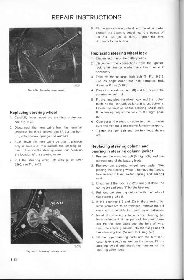
Fia. _3_. Remo,i,g c,a_h guard 4. Press in the rubber bush (8) and lift forward the
steering wheel lock.
5. fit the new steer_ng wheel lock and the rubber
bush. Fit the lock bolt so far that it just bottomS.
_heck the funct_on of the steering wheel lock.
_epIacing s_ee_i_g whee_ If necessary adjust the lock to the right posi-
1 . _arefuIIy Iever Ioose rhe padd_ng protect_on, tlOn_
,ee F_g. 6-32. 6. _onnect all the electr_c cables and test to make
b F h _ sure the var_ous components function properly.
2. D_,Ço,,ect fhe horn Ça _g fom t e termlna .
u,,ç,ew the th,ee ,,,ew, ,,d __,_ o,t the ho,, 7. Tighten the loCk bolt until the heK head shearS
,_,g w_th gÇ,ew,. ,p,_,gg a,d waghe,,. off.
3. Push down the horn cable so that it projects
only a couple of mm outside the steering co- _ep_acing gtee_ing co_u_n and
Iumn. UnsCrew the Steering wheel nut. Mark UP bearing in gteering co_u_n jacket
the location of the steer_ng wheel. b _ (_ F 6 34) d d.
1 . RemoVe the Clamplng O t , Ig. - an IS-
4 Pull the steer_ng wheel off w1th puller SVO co,,eçt one of the battery _eads.
2263, See Fig. 6-33. 2. _emove the gtee,;,g whee_. gee ,,de, __Re_
placing the steering wheel''. Remove the flange.
turn indicator lever sw_tch, spring and bearing
seat.
3. Disconnect the lock ring (23) and pull down the
spring (6) and seat (7) for the bearing.
4. Pull out the steering column with the help of
the steering wheel.
_'. If the bearings (I3 and 22) _n the steering Co-
Iumn jacket are to be replaced. remoue the old
oneg with a su_table tool such as an eKtractor.
6. Insert the steering column in the steering co-
Iumn jacket and fit the parts of the lower bear-
ing. fit the horn cable with the help of w_re.
Push the steering column into the flange and fit
the clamping bolt (5) and fock ring (23).
7. f1t the upper be3ring parfs and the turn indi-
cator lever switch as well as the flange. fit the
vo_,Lu,__ steering wheel and check the function of the
F.,g. 6.33. _e_,,.,,g ,,,e,.,,g w_,e_ steer_ng wheel lock.
6_ 18
|

