 |

|
 |


Begin OCR Text:
6 fit the new rubber bushes and sleeves on the 7 Lower the jašk and p_aše _t under the w_ghb
_ _ One
WiShbone shaft_ at the outer edge of the sprjng. CareFu__y j_ašk
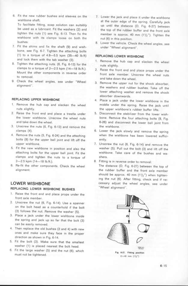
TO faci litate fitting soap solution can suitably up until the d istanše (D F_g 6 27) be_ee
_ , . - n
be USed as a lubricant fit the washers (2) and the top of the rubber buffer and the Front ax_e
_
tighten the nuts (1 ) see fig 6- 1 3 Then fiK the member is approx qo mm (_ 1/ __) Tighte the
_ _ _ _ . n
wiShbone with its clamps loose on both the nut (6) in this position.
bUSheS_ 8. Lower the vehicle. Check the whee_ ang_eg. see
7. fit the sh ims and fix the shaft (9) and wish- under '' Wheel a_ ignment__.
bone, see fig. 6_7. Tighten the attaching bolts
C1 ) to a torque of 4.8-5.5 kpm (3f4O Ib.ft) REPLACl NG LoWER w_S HBoNE
and lock them with the tab washer (3) 1 ffemove th h b d _ k h h _
_ _ e U cap an s ac en t e w ee
8 Tighten the attaching nuts (6 fig 6-1 3) for the n,tg g__,ght_
' ' ' _ Y_
ClamPS to a tOrque of 2_2 5 kpm (1 _1 8 Ib ft ) 2 Raige the Fr nt e d d _ d h
_ _ _ _ _ o n an p ace props un er t e
MOunt the other components in reverse order Front ax_e membe u th h _
r. nsCrew e w ee nutg
tO fem OVal d tak d th h _
_ an e oWn e W ee .
9 Check the wheel angles see under '' Wheel 3 Remove th pp t F th h k b b
' _ _ e U ef nu or e s oš a sor er,
al _gnment'' the wagher and bb b h T k FF th
_ s rU er ug eg. a e o e
Iower aftaching washer and remove the shošk
absorber downwards.
REPLACING UPPER WIS HBOME 4 Place a jack under the _ower w_ghbone _n the
_
1 . Remove the hub šap and g_ašken the whee_ middle under the spring. Ra ise the jašk unti_
nuts g_ight_y. the upper wishbone's rubber buffer _ifis.
2. Raise the front end and p_ace a tregt_e under 5_ DisConnect the stabi lizer from the lower wish-
the lower wishbone. Ungšrew the whee_ nutg bone_ Remove the four attach ing bolts (8, Fig.
and take down the whee_. 6-26) and disconnect the Iower ba__ joint from
3. Unscrew the nuts (˘, fig. 6_1 3) and remove the the Wi Shbone,
clamps (4). 6_ LoWer the jack s1owly and remove the spring
4. Remove the n uts (5, fig. 6-24) and the attašhing When the wishbone has been lowered suffici-
bolts (8) for the upper bal I joint and l ift off the entIY_
upper wighbone. 7_ Un SCfew the nut (6, fig. 6-1 4) and remove the
5. Fit the new wishbone in pogition and a_go the waSher (5). Pull out the bolt (3) and lift off the
attaching bolts for the upper ba __ jo_nt. F_t the wi Shbone. Take care of the bushes and wa-
clamps and tighten the nutg to a torque oF SherS_
2-2.5 kpm (1 4-1 g _b._.). 8. Fitting is in reverse order to remova I.
6. Re-fit the other components. Chešk the whee_ The distance (D. Fig. 6-27) between the top of
alignment. the rubber buffer and the front ax_e member
shOuld be approK. 4O mm (1 1/j '') when tighten-
ing the nut (6). After fitting. check and if ne-
_OWE_ W__ H _O_ E CeSSarY adiust the wheel angles, see under
LAC '' Wheel a Iignment''
REP l NG LOWER WlSHBONE BUSHES '
1 . ffaise the front end and p Iace props under the
front aKle member.
2. Unscrew the nut (6. fig. 6- 1 4). Use a spanner
on the bolt head as a counterhold if the bo_t
C3) follows the nut. Remove the washer (f).
3. Place a jack under the lower wýshbone ingide
the sPring and jack up so far that the bolt (3)
can be easily removed.
4. Then replace the old bushes (2 and 4) with new
ones and make sure they face in the proper
direction as shown in fig. 6-1 4.
5. Fit the bolt (3). Make sure that the sma Ilest
waSher (1 ) is placed nearest the boIt head. ygL_v_
6. fit the large washer (5) and the nut (6) which
' Flg. 6-27. Flttlng po_ition
m USt nOt be tightened. D=4o __ (i _/,__) 6 ; 1 5
|

