 |

|
 |


Begin OCR Text:
either increase or reduce the number of sh_ims
equaIIy fo_ both bolts. More positive camber is
obtained by removing shims and negative camber
by _ncreas_ng the number of shims.
The shim thickness required to alter the angIe
to a ce__tain e_tent is shown in the diagram in fig.
_-9. Shims are stocked in thicknesses of O.15-O5
-1._3.O and 6.O mm (O.OO_O.O2O-O.O3_O.12O
and O 24O''). The total thickness of shims at each
bolt may not e_ceed 12 mm (O.48''). The difference
in thickness between the shims at the front and
rear bolts may be ma_. 2.5 mm (O.1''). Note that j v,,o,L,v,o,
an eqUal nUmber of Shims muSt be removed or F_g. 6-__. Adj_,,__,,g ,__..,,,. _,,. ,,___,_ _,,_
added at both the bolts if the camber is not to be 1 Ad_us__ng screw
altered.
After adjust_ng tighten the bolts to a torque of 5.5-
7 O kpm (4O-5O Ib.ft.) and lock them.
In order to save time and labour adjust the caster
and šamber at the same t_me by remov_ng or add- ADlUSTING TOE_lN
_ng shims for the camber and altering the number The toe-in should be O4 mm (O-O.16''). Incor-
of shims for the caster. for e_ample, if the camber rect toe-in is adjusted by slackening the locknuts
_s increased O.6' and the caster 1/4', first remove on the tie rod, after which the rod is turned in the
2.5 mm (O.1'') in shims at both the bolts and move required d_rect_on. The d_stance between the tyres
O.15 mm (O.OO6'') in shim thickness from the front at the front is reduced, that is to say, toe-in _s
to the rear bolt. increased by turning the tie_rod in the normal
direction of rotation of the wheels. __ighten the
Iocknut after adjustment to a torQue of 7.f9.O
kpm (55-65 Ib.ft.).
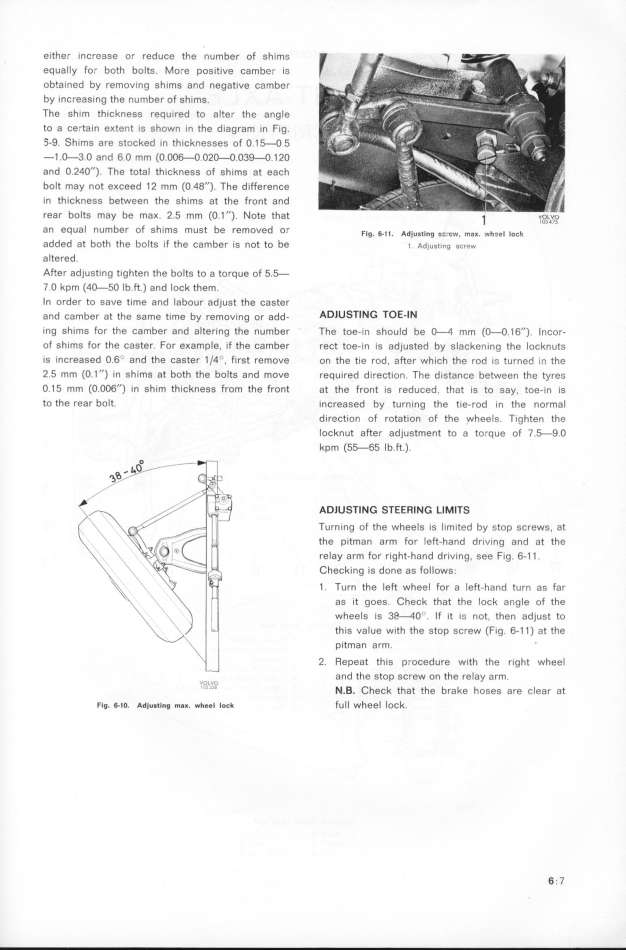
ADlUSTING STEERING LIMITS
Turning of the wheels is lim_ted by stop screws, at
the pitman arm for left_hand dr_ving and at fhe
reIay arm for right-hand driving, see fig. 6-11.
Checking is done as follows_.
1. Turn the Ieft wheel for a left_hand turn as far
as it goes. Check that the lock angle of the
wheels is 3P_4O'. If it i__ not, then adjust to
this value with the stop screw (Fig. ti11) at the
pitman arm.
2. Repeat this procedure with the r_ght wheel
,o, u and the stop screw on the relay arm.
' _'_' N.B. Chešk that fhe brake hoses are clear at
Fig. 8_o. Adju__ing m8_. __ee_ ioc_ full wheel lock. 6.7
|

