 |

|
 |


Begin OCR Text:
(
_
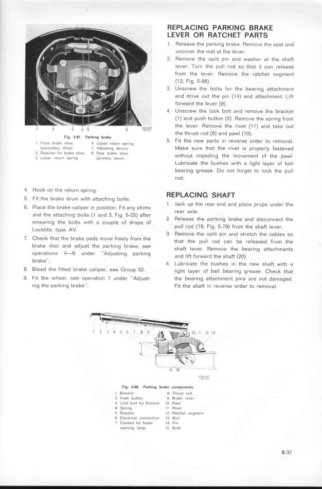
REPLAGING PARKING BRAKE
LEVER OR RATCHET PARTS
1 Release the parh_ng brake Remove the seat and
uncover the maf at the lever
2 Remove the spl_t p_n and washer at the shaft
Iever Turn the pull rod so that _t can release
from the lever Remove the ratchet segment
(1 2, Fig. 5-88)
3. Unscrew the bolts for the bear_ng attachment
and dr_ve out the pin (14) and attachment Lift
forward the lever (9)
4 Unscrew the _ock boIt and remove the bracket
(1) and push button (2) Remove the spring from
v, the lever Remove the r_vet (1 1 ) and take out
'' the thrust rod (8) and pawl (1 O)
Flg 5_8l. Parking bra_e F d _
5 _t the new parts _n reverse or er to remova
l front hrake shoe 4 Upper return sprinq h _ F d
(gecondary shoe_ s Adjug__ng dev_ce Make sure that t e fivet IS prOpef y aStene
Z Re_aineJ fUr brake shoe 6 Rear brake Shoe th t d th em t F th pa _
w_ ou _mpe _ng e mov en o e w
3 Lower return spr_no _pr_mary shop) Lubricate the bushes w_th a lighf layer of ball
bearing grease Do not forget to lock the pull
rod.
4 Hook on the return spr_ng REPLACING SHAFT
5 f_t the brake drum with attach_ng bolts 1 . lack up the rear end and place props under the
6 Place the brake cal_per in pos_t_on fit any sh_ms rear a_Ie
and the attach_ng bolts (t and 3 Fig 5-25) after
' 2. Release the park_ng brake and d_sconnect the
smearing the bolts w_th a couple of drops of pull rod (1 9, Fig 5-79) from the shaft lever
Locktite type AV b
' 3. Remove the split pin and stretch the ca les so
7 Check that the brake pads move freely from the th t th __ d b _ d F th
a e pu ro can e re ease rom e
brahe d_sC and adjust the parh_ng brake see h Ft _ R th b tt h t
_ s a ever emove e ear_ng a ac men S
operations _6 under _Adjust_ng pafklng d _ Ft F d th h Ft (2o)
an i O_ar e S a
brake'' q _ b _ t th b h the ha_ th a_ . u riCa e e US eS In neW S Wl
8 Bleed the fitted brake cal_per, see Group 52_ __ght layer of bal_ bearing grease Chešk that
g f_t the wheel, see operat_on 7 under _Adjust- the bear_ng attachment pinS are not damaged
_ng the parking brake'' fit the shaft _n reverse order to removal
l5 l4 h__L,VO
Fig. _88. Park_ng brake components
_ g_aeke_ 8 Thrusl rnd
2 Pu__h butto_ 9 Brake leVer
3 _ošk bDlt for brdcket lO Pawl
4 Spring ll Rivet
5 g_aeket l2 RatChet Seg_ent
6 __ešt_išal šonnection 13 Bolt
7 _o__ašt for brake l4 P_n
warning lamp 15 Bush 5 37
|

