 |

|
 |


Begin OCR Text:
_
p A _ K _ _ _
B _ A K E v_uoj__dvj_o_j_
' __OU_ __
D E_ _ _ _ ___ O N
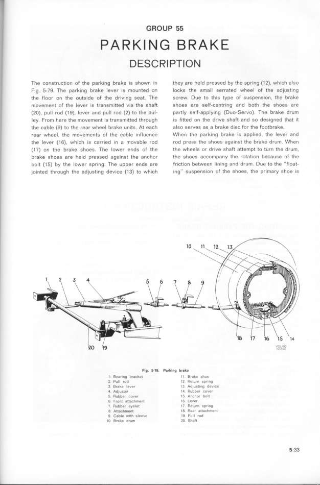
The construction of the parking brake is shown in they are held pressed by the spring (1 2). which also
fig. 5-79. The parking brake lever is mounted on locks the smaIl serrated wheel of the adjusting
the floor on the outside of the driving seat. The screw. Due to this type of suspension, the brake
movement of the lever is transmitted via the shaft shoes are self-centring and both the shoes are
(2O), pull rod (1 9), lever and pull rod (2) to the pul- partly self-applying (Duo_Servo). The brake drum
Iey. from here the movement is transmitted through is fitted on the drive shaft and so designed that it
the cable (9) to the rear wheel brake units. At each also serves as a brake disc for the footbrake.
rear wheel, the movements of the cable influence When the parking brake is applied. the lever and
the lever (1 6), which is carried in a movable rod rod press the shoes against the brahe drum. When
(1 7) on the brake shoes. The lower ends of the the wheels or drive shaft attempt to turn the drum,
brake shoes are held pressed against the anchor the shoes accompany the rotation because of the
bolt (1 5) by the lower spring. The upper ends are friction between lining and drum. Due fo the _float-
jointed through the adjusting device (1 3) to which ing'' suspension of the shoes, the primary shoe is
Fig. S-79. P$rking brake
1 . Bearing bracket ll. Brake shoe
Z. Pull rod 12. Return spring
3. Brake lever l3. Adjusting device
4 AdjuGter 14 Rubber Cover
f. Rubber cover l5. AnChor bolt
6. FrDnt attachment l6. Lever
7 Rubber eyelet I7. Return Spring
0. A__a_h_e__ l0. Rear att6chmenl
g. _ab_e wi_h gleeue 10. Pull rod
IO. Brake drum 2O. Shaft _;33
|

