|

|
 |


Begin OCR Text:
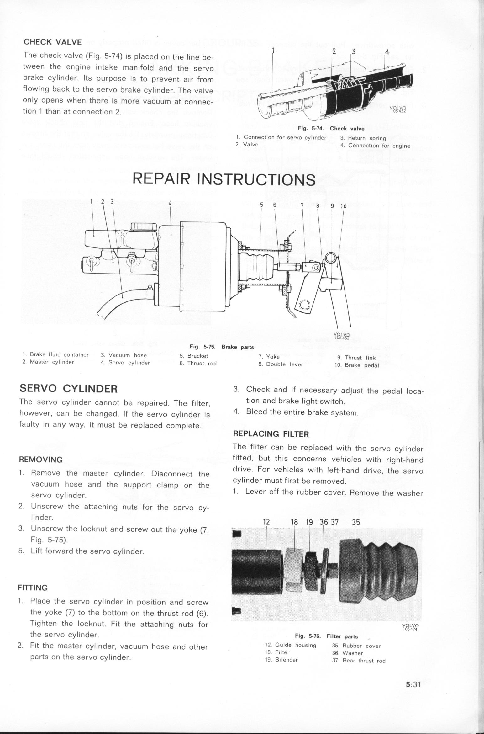
CHECK VALVE
The check valve (fig. 5-74) is plaþed on the __ne be-
tWeen the engine intake manifo_d and the gervo
brake cylinder. Ifs purpose is to prevent a_r From
flow_ng back to the servo brake þy_inder. The va_ve
Only opens when there _s more vaþuum at þonneþ-
t_i_n 1 than at þonneþ__on 2. Fig. 5-l_. Che__ v8lve
l Connection for servo cylinder 3 Re_urn gpr_ng
Z Valve 4 Conneo__on For eng_ne
R E PA _ R _ _ __ R U ___ O _ _ ;_p_,u,_
Fig, _lf. Brake part_
1 Brake fluid _ontainer 3 Vaouu_ _oge 5 _ra__e_ _. yo_e g _brug_ __.n_
2 MaSter cylinder 4 _e_o cy_inder 6 _brug_ _od g _oub_e _ever _D g _ d _
ra e Pe a
SE RVO CYLl N DER 3. Check and if necessa,y ad)ugt the peda_ _oþa-
The servo cy_inder þannot be repa_red. The f__ter, t_On and brake light switch.
however, þan be þhanged. _f the gervo þy___nde, _,g 4_ Bleed the entire brake system.
faulty in any way. it must be replaced comp_ete. REPLACING FILTER
l
The filter can be replaced with the gervo þy_inder
REMovlN_ fltted, but this concerns vehicles with right-hand
_ Re th t _ d D. h drive. for vehicles with leFt_hand drive the gervo
_ mOVe e maS er Cy In ef. ISCOnneCt t e _
h d th _ h Cylinder must first be removed
VaCuum OSe an e SUppOrt C amp on t e _ '
gervo þy__nder. 1 _ eVer off the rubber cover. Remove the waghe_,
2_ UnsCrew the attaching nuts for the servo þy- ,
linder. __ _g _g 36 3_ 3_ _
3 UnSCrew the locknut and screw out the yoke (7. _ _
Fig. 5-75).
5. Lift forward the servo cyIinder.
i
FITTING
1 . Place the servo cylinder in pogition and gþ,ew
the yoke C7) to the bottom on the thrust ,od (6). _
Tighten the locknut f_t the attaþh_ng nutg fo, vo_vo
h ' IO54f4
t e servo cyl_nder. FIg. __6. F_i__ pg_$
2. Fit the magter þy_inder, vaþuum hoge and other 12 Guide hous_ng 35 Rubber cover
t th _. d 18 Filter 36 Wagber
par S On e Se,VO Cy in er. _g ____ence, 3_ _ear _brug_ rod f_.31
|