 |

|
 |


Begin OCR Text:
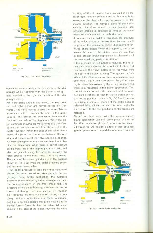
shutting off the air supply. The pressure beh ind the
diaphragm rema ins constant and is thus unable to ,
overcome the hydraul ic counterpressure in the
master cylinder. The movable parts of the servo
cylinder, therefore, remain in this pos ition , and
constant braking is obtained as long as the same
pressure is ma intained on the brake pedal .
lf pressure on the pedal is increased, the pressure
of the valve piston on the reaction d isc centre will
be greater, this causing a certa in d isplacement for-
wards of the piston. When th is happens. the valve
Ieaves the seat of the piston, more air can flow
i n and greater brake appIication is obta ined unti l
fhe new equal izing position is attained.
__ _ If the pressure on the pedal is reduced, the reac-
tion disc centre šan be thrust out stitl further and
Ma__ PartIa_ AimoSpherIo '
vacuum presseur thi S Ca USeS the VaIVe pi Ston to lift the Va IVe from
the seat in the guide housing. The spaces on both
Fig_ f72_ Full b_a_e 8pplitatloIl s__des oF the d_iaphragm are thereby connected w__th
each other, equal pressure arises, the gu ide hous-
ing is moved backwards by the spring pressure and
equivalent vacuum exists on both s ides of the dia- there is a reduction in the brake application. This
phragm which. together with the gu ide housing, is procedure also reduces the confraction of the reac_
held pressed to the right end pos ition of the d ia- tion disc perphery. so that the valve pÝston can re-
phragm spring. turn to the position shown i n Fig. 5-73 and the new
When the brake pedal is depressed , the rear thrust equal izing position is reached. If the brake pedal is
rod and valve piston are moved to the left (for- released futly, all the parts of the servo cyl linder
wards). The ualve spring causes the value plate to are returned to the rest position and the brakes are
move also unti l it reaches the seat in the g uide released.
housi ng. This closes the connection between the Should any fault occur with the vacuum supply,
front and rear side of the diaphragm. When the pis- brake application can sti Il stake place due to the
ton contin ues mouing, its movements are transferr- fact that the seruo cyli nder functions as an eKtend-
ed via the reaštion disc and front thrust rod to the ed thrust rod. As no servo effect is then obtained.
master cyli nder. When the seat of the valve piston greater pressure on the pedal is of course requi red.
Ieaves the plate, the connection between the rear
side and the centre of the valve section is opened .
Ai r from atmospheric pressure can then ffow in be_
hind the diaphragm. When there is partial vacuum
',
on the front side of the diaphragm, it is moved, and
also the guide housing. forwards. l n th is way. the
force appl ied to the front thruet rod is increased.
The parts of the servo cyl inder are in the pos ition
shown in fig. 5-72 when the pedal pressure proui-
des maKimum servo effect.
If the pedal pressure is less than that mentioned
above, the same procedure takes place in the be-
ginning. During brake appl ication. the hydraulic
pressure in the master cylinder increases and aIso
the counterpressure on the front thrust rod. The g
pressure of the gu ide housing is transmitted to the
thrust rod through the outer part of the reaction
disc. Because the d isc is made of rubber, its peri-
phery contracts whi le its centre tends to eKpand, i- __ _
see F__g _-73 Th_g šauseg the gu__de hous_ng to be Ma_. partial Partial Almospheric
' _ F h h d vaCuUm vaCUUm PreSSUrC
moVed furthef ofWardS t an t e Val Ve pjSton an
results in the seat of the piston reaching the valve F_g. f73. pa_iai b_a_e appi_c8_ion
5;3O
|

