|
|
 |


Begin OCR Text:
A u x _
)
___
_ _ A _ y B _ A K E _ y _ _ E _
G RO U P 54
D E_ _ R l __ l O N
t I g 1 g
' _' l P_I_ / ' /_'_ ' _l'I l ' _ l
. i _. _ (3 (l _ _ __
. i _ /'_
' _ i , i,
,___p_ _ / ___J ( _' l _ _ ,
' _i , _y_ ě _ í ,_ , ' _ _
2 o 2 1 2'2 2 3 2 _ Z 5 2/6 2 7 28 29 3o 31 3'2 33 3 _ 3 5 3_6 3 7
VOLVO
l O_'446
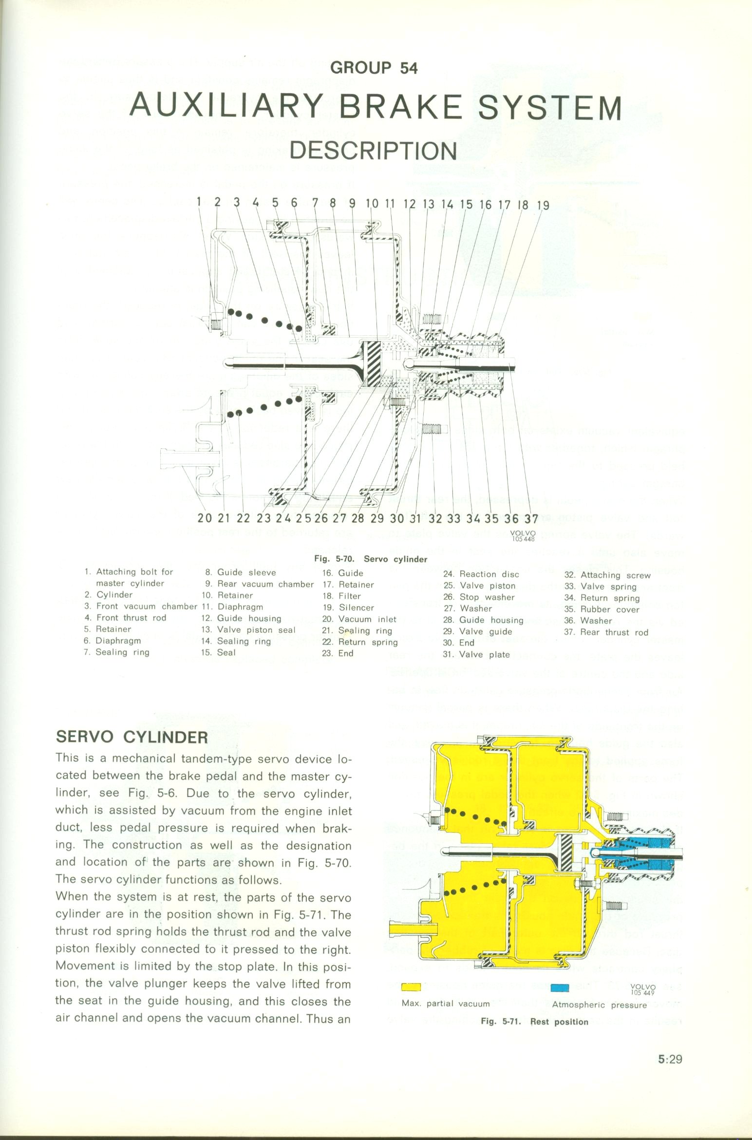
Fl$ _7O. Se_o cyllnder
l Attaching bDlt for 8 Guide sleeve l6 Guide 24 Reaction d_sc 32 Attaching screw
master cylinder 9 Rear vacuum chamber l7 Reta_ner 25 Valve piston 33 Value spring
2 Cylinder l O Reta_ner l8 Filter 26 Stop washer 34 Return apring
3 Front vacuum chamber l l D_aphragm t9 S_lencer Z7 Washer 35 Rubber cover
4 front thrust rod l 2 Guide housing 2O Vacuum inlet 28 Guide housing 36 Waaher
5 Retainer l3 ValvE piston seal 21 Spaling ring 29 Valve gUidE 3T Rfar thrust rod
6 Diaphragm 1 O Seal_ng ring 22 Return spring 3O End
7 Sealing ring l5 Seal 23 End 3l Value plate
S E RVO CY Ll N D E R
Th_s _s a mechan ical tandem-type servo dev_ce lo-
cated between the brake pedal and the master cy-
l _nder, see F_g 5_6 Due to the servo cyl_ nder,
which is assisted by vacuum from the eng _ne _ nlet
duct, less pedal pressure _s req uired when brak-
ing The construction as wel l as the designat_on
and locat_on of the parts are shown in F_g 5_7O
The servo cylinder funct_ons as fol lows
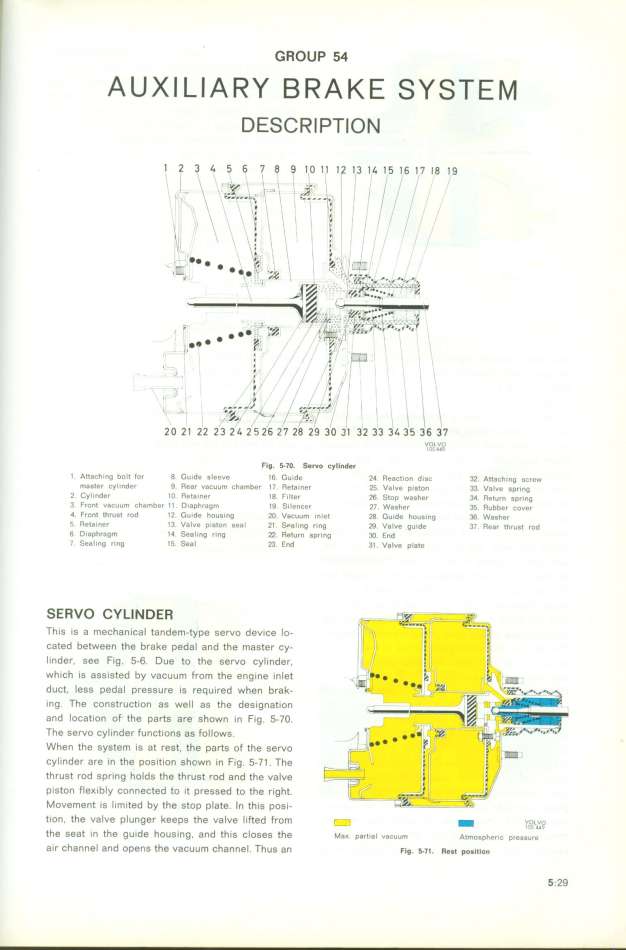
When the system is at rest, the parfs of the servo
cyli nder are in the pos_t_on shown in Fig 5-7 1 The
thrust rod spr_ng holds the thrust rod and the valve
p_ston fle_ibly connected to _t pressed to the right
Movement _s limited by the stop plate In th_s pos_-
f_on the valve plunger keeps the valve lifted from r _ _ voLvo
' - _05 d4q
the seat _n the guide hous_ng, and this closes the Max partia_ vacuum Atmosp_eric pressure
a_r Channel and openS the vaCUUm Channel ThuS an Fig t__I. ReDt poDition 5_29
|