 |
|
 |


Begin OCR Text:
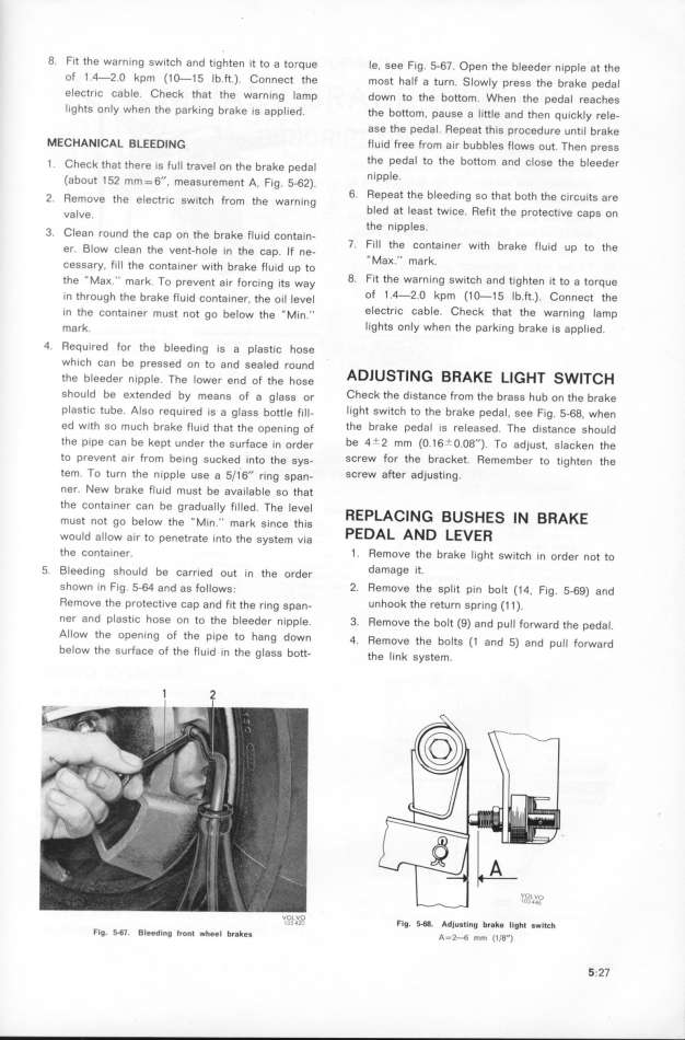
8_ Fit the warni'ng switch and tig'hten it to a torque Ie, see Fig. 5-67. Open the b_eeder nipp_e ae ehe
of 1_4-2_O kpm (1O-15 Ib.ft.). Connect the most half a turn. Slowly press the brake pedal
electric Cable, Check thaf the warning lamp down to the boftom. When the peda_ reaþhes
lightS only when the parking brake is appIied. the bottom, pause a little and then quiþk_y re_e-
ase the pedaI. Repeat this procedure until brake
MECHA__CA_ __EeD_w_ fIuid free from air bubbles flows out. Then press
Ch k h h F the pedal to the bottom and close the bIeeder
1. eC t at t ere is ull traveI on the brake pedaI
( b ,, nipple
a out 152 mm=6 , measurement A, Fig. 5-62). '
2 ff h _ F 6. Repeat the bleeding so that both the circuits are
. emoVe t e e eCtric SwitCh fom the warning
va_ve bled at least twice. Refit the protective caps on
_ ehe nipples.
3. CIean round the cap on the brake fluid contain-
g_ _ 7. fill the Container with brake fluid up eo ehe
er. ow c ean the vent-hole in the cap If ne-
F _ ''MaK '' mark
Cessary. ill the container with brake fluid up to ' '
th __M __ k T e _ F _ _e 8 fit the Wafning SWitCh and eighten ie eo a torquee aK ma, o preven ai, o,þ ng i g wa _
. . l y
i_n eh gh eh b k F_ _d e _ eh __ _ _ of 1 4-2 O kpm (1_15 Ib ft) Connect the
rOU e ra e Ul COn alner, e Ol eVe ' ' _ _ '
in the onea_ t t b _ eh __M_ __ eleCtriC Cable CheCk that the Warning lamp
C Iner mUS nO gO e OW e In. '
ma,k. Iights only when the parking brake is applied.
4. Required for the bleeding is a plastic hose
which can be pressed on to and sealed round AD_u_T___ __ Ke
ehe b_eede, n_pp_ Th _ d F eh h A L__HT _WjT_H
l e_ e OWef en O e OSe
shouId be eKtended by means of a glags o, CheCk the distance from the brass hub on the brake
plasfic tube. Also required js a glasg bottle F_l_- light SwitCh to the brake pedal, see fig. 5-68. when
ed with so much brake flujd thae ehe opening oF the brake pedal is released. The distanCe should
the pipe can be kepe under ehe su,faþe in o,de, be 4t2 mm (O.16tO.O8''). To adjust, sIacken the
to prevent air from being sucked ineo the gyg- SCreW for the bracket. Remember to tighten the
tem. To turn the nipp_e use a 5__6'I ring span- SCreW after adjuSting.
ner. New brake fluid must be availab_e so thae
the container can be gradually fiIled. The Ieuel _EpiA____ _u_HE_ __ __AKE
e e b _ th __M. __ k , eh,
mUS no go e ow e in. mar since is pEDAi A_D iEvE_
wou_d a__ow a_ e p e e _ e th t _
Ir O ene ra e In O e SyS em Vta
the þontainer. 1. Remove the brake light switch in order not to
5 g_eed;ng ghou_d be þar _ d o e _ th d damage it_
_ rle U In e Or ef
shown in Fig. 5-64 and as fo__owg_. 2, Remoue the spIit pin bolt (14, Fig. 5_6g) and
Remove the proteþtive þap and fie ehe ,ing gpan- Unhook the return spring (11).
ner and plaStic hoSe on to the bleeder nipple 3 Remove the bolt (g) and pu__ forwa,d ehe peda__ _ .
Allow the opening of fhe pipe to hang down 4 ffemo e ehe b lt (_ d 5_ d ll F d
. U o S an , an pu orwar
below the surface of the fluid in the g_ass boee eh __ k e
- e In SyS em.
1 2 U_OOjL4V2OC Fig. f_W. Adlusting br8ke Ilght swit_h
Fig_ _6l_ Bleeding tront wheel brakes A=__ __ (__$_I) 5.27
|

