 |

|
 |


Begin OCR Text:
U__O__QVdO4
Fig. f_63. Connettlng unll U_f__l4U_o_
Flg. 5_. Bleeding _ront _heel brake unit
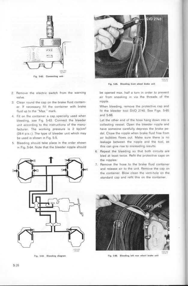
2 Remove the electr_c switch from the warning be opened maK half a turn in order to prevent
valve air from sneaking _n v_a the threads of the
3 C_ean round the cap on the brake f_u_d çontain_ nIPPle
er If necessary f_ll the conta_ner with brake When bleeding, remove the protective cap and
flu1d up to the ''MaK '' mark f_t the bleeder tool SVO 274O See figs 5-65
q F_t on the conta_ner a cap spec_a__y used when and 5-66
bleed_ng, see f_g 5-63 Connect the bleeder Let the other end of the hose hang down into a
unit according to the instructions of the manu- collect_ng vessel Open the bleeder nipple and
facturer _he work_ng pressure _s _ kp/çm2 have someone çarefu__y depress the brake pe-
(28 4 p s 1 ) The type of bleeder un_t which may dal Close the nlpple when brake flu_d free from
be used is shown in Fig 5-5 a_r bubbles flows out Make sure there _s no
5 __eed_ng shou_d take p_açe _n the order shown leakage between the nipple and the tool, as
_n Fig 5_64 _ote that the b_eeder nipp_e shou_d th_S Can give rISe to m_sleading reSultS
6 Repeat the bleeding so that both circuits are
bled at least twIce Ref_t the protect_ve caps on
the nipples
7 Remoue the hose to the brake fluid container
_ q and release a_r to the un_t ffemove the cap on
the conta_ner Blow clean the vent-hoIe on the
standard cap and refit th_s on the container
VU_VO
l j44i vo_Vo
l _4__
Fig 5_64 Bleeding diagram Fig 5-66 Bleed_ng le_ rear wheel br8ke unit
5 26
|

