 |

|
 |


Begin OCR Text:
l NSTALLING
j _ g 1 1 1 O 1 5 _ th b k _ EUR th b k h ee
çrew e ra e va ve on O e ra e OSe, S
f_g 5-58 Place the valve _n posit_on and CheCk
thae there _s no tens_on in the hose f_t the attach-
_ng bolts and connect up the brake pipe T_ghten
the connections BIeed the brake system
'' .
ADlUSTl NG
The adjusting screw (1 2. F_g 5_41 ) is not intended
for adjusting in the normal mean _ng of the
word
_fg funçf_on _g to balançe the variations in the manu-
z o g z j j g jz j j factur_ng. The carefully checked adjustment made
'i_'i_'_ at the qnqtial assembl _ng _s generally sufficient for
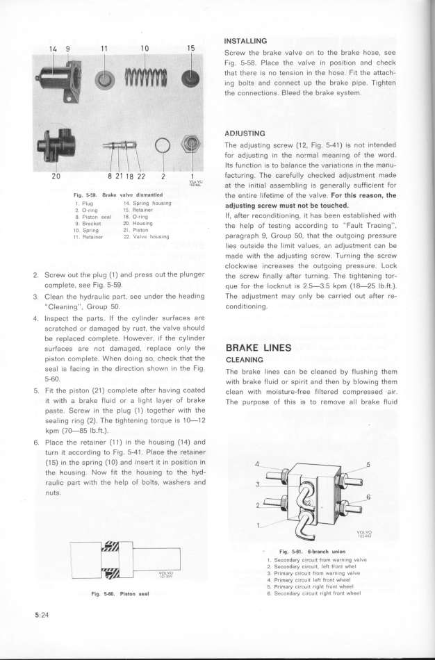
F_g __sa Bra_e valve d_smantled the entire __fetime of the valve For thiS feaGon_ the
_ P_ug 14 S_,ing hoUSlng adjug_ing g_few _ugf no_ be fou_hed.
2 O.,i_g l5 Refainer d h b b_ h d th
g p_,,,,, ,,,_ _g o ,,,g _f, afier recon itioning, _t as een esta _s e w_
9 Bracket 2O HoUSing the he_p of tegt_ng aççord _ng to _ Fau _f Traçing'',
l O Sp,ing 2l P_Ston h g _ 5o h h t
i i _,_,_,,, 22 vaIve hous_ng paragrap . roup . t at t e oU golng PreS SUre
_ies outsqde the Iqmit val ues. an ad)ustment Can be
made w_th the adjust_ng screw Turning the screw
cloçkwise increases the outgoing pressure Lock
2 _crew out the pl ug (1 ) and press out the pl Un9er the screw f_nal Iy after turning The tightening tor-
complete, see Fig 5-59 que for the locknut is 2 f3 5 kpm (1 _25 Ib ft )
3 __ean fhe hydrau_ _ç parf gee under EURhe head_ng The adjustment may only be Carr_ed out aftef re-
_ __ean_ng'', _roup 5O cond_t_ On Ing
4 lnspect the parts If the cyl _nder surfaceS are
gçratçhed or damaged by rust, the valve should
be reptaced complete However. _f the cyl inder
surfaces are not damaged. replace only the B RAKE Ll _ ES
p_gton complete When do_ng so, check that the _LEANl NG
gea_ _s faç_ng in the direction shown _n the Fig Th b k _ b _ d b F_ h g ehem
e fa e IneS Can e C eane y US In
5-6O_ w_th brake flu_d or sp_riEUR and then by bIow_ng them
5 F_t the piston (2t ) complete after having coated ç_ean wqth moisture-free filtered compressed air ;
qt w_th a brake flu_d or a l ight layer of brake The purpose of th_s _s to remove al l brake fluid
paste Screw in the pl ug (1 ) together with the
seal ing ring (2) The tighten _ng torque _s 1 _1 2
kpm (7_85 lb ft ).
6 Place the reta_ner (1 1 ) _n the housing (1 4) and
turn _t aCCording to F_g 5-41 PIace the reta_ner
(1 5) _n the spr_ng (1 O) and _nsert it in pos_tl On In _
the _ous_ng Now fit the housing to the hyd-
raul_ç part with the help of boltS. washers and _
nuts Z
F_g. 5_$l. _br8_ch u_lo_
l Secondary CirCuit from warn_ng valve
2 _eco,da,y c_,cu_t left front whel
3 Pr_m6y C_fCu_t from warning valve
4 Pr_m8y C_,Cuit left front wheel
f Pr_may circuit right front wheel
F_g. _. pig_o_ geg_ 6 SeConday c_rcuit r_ght front wheel
5 24
|

