 |

|
 |


Begin OCR Text:
_ _i__ __ _ ,j
_. _g,.L_,o._
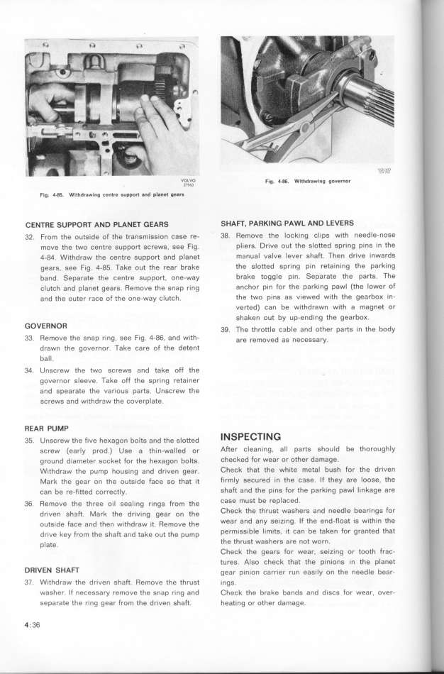
VzO_L_V63O F__g. _.g$. w___d_aw___g gove__o_
Fig. 4_85. Withd_awing centre suppo_t 8nd pIanet ge8ra .
CENTRE SUPPORT AND PLANET GEAffS SHAFT, PARKING PAWL AND LEVERS
32. From the outside of the transmission case re- 38. Remove the locking clips with needle-nose
move the two centre support screws, see Fig. pliers. Drive out the slotted spring pins in the
4-84. Withdraw the centre support and planet manual valve lever shaft. Then drive inwards
gears. see Fig. 4-85. Take out the rear brake the slotted spring pin retaining the parking
band. Separate the centre support. one_way brake toggle pin. Separate the parts. The
clutch and planet gears. Remove the snap ring anchor Pin for the parking pawl (the lower of
and the outer r3ce of the one-way clutch. the two pins as viewed with the gearboK in-
verted) can be withdrawn with a magnet or
shaken out by up-ending the gearboK.
GOVERNOR 3g _he t_rott_e š3b_e and other pa_g ._n the body
33. Remove the snap ring. see fig. 4-86, and with- ' are removed ag nešeggay
drawn the governor. Take šare of the detent '
ball.
34. Unscrew the two screws and take off the
governor sleeve. Take off the spring retainer
and spearate the various parfs. Unscrew the
screws and withdraw the coverplate.
ffEAR PUMP
35. Unscrew the five heKagon boltg and the g_otted INSPECTING
screw (early prod.) Use a thin_walled or After cleaning. all parts should be thoroughly
ground diameter socket for the heKagon bolte. checked for wear or other damage.
Withdraw the pump housing and driven gear. Check that the white metal bush for the driven
Mar'x the gear on the outside face so that it firmly secured in the c3se. If they are loose, the
can be re-fitted correctly. shaft and the pinS for the parking pawl linkage are
36. Remove the three o__ gea___ng r__ngg From the CaSe mUSt be replaCed.
dr_ven gh3Ft. _ark the dr_v_,ng gear on the CheCk the thrUSt WaSherS and needle bearingS for
outg_de faše and then w_thdraw __t. Remove the Wear and any Seizing. If the end-float iS within the
dr_ve key From the gha_ and take o,t the p,mp permiSS_ble IjmitS, it Can be taken for granted that
p_ate. the thrUSt waShefS are not wofn.
Check the gears for wear, eeizing or tooth frac-
tures. Also check that the pinions in the planet
DRIVEN SHAFT gear p_n_on carr._er run eag.__y on the need_e bear. '
37, Withdraw the driven shaft. Remove the thrugt _ngg. '
Washer If necessary remove the snap ring and Check the brake bandg and d_gcg for wear, over- I
Separate the ring gear from the driven sha_. heating or other damage.
4__36 _
|

