 |

|
 |


Begin OCR Text:
__
_ _
__
A
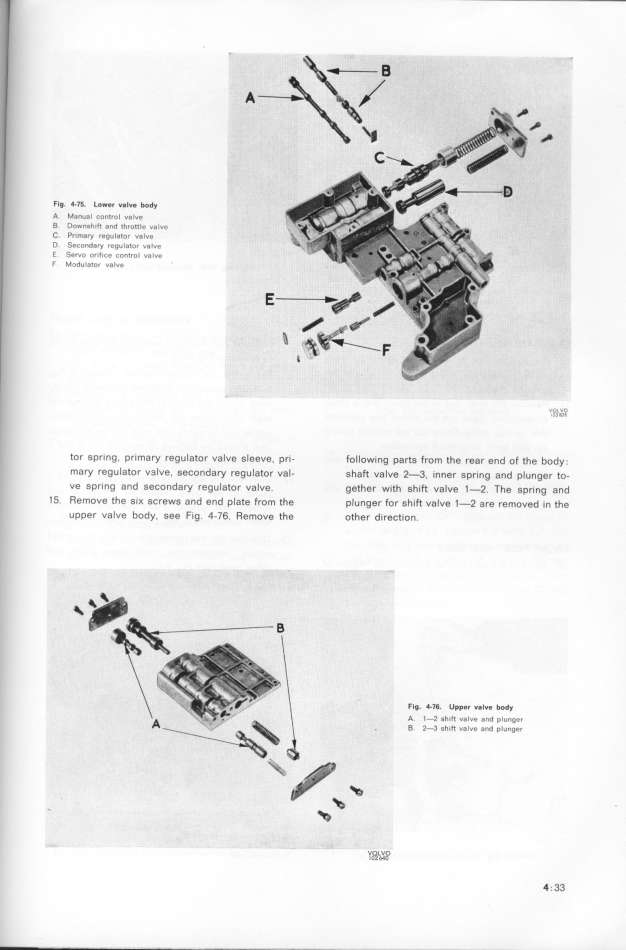
FI$ _-7f_ Lo_er v_lve body
A Manual Control vaIve
B Downshift and _hrottle va_ve
C Pr_mary regularor valve
D SecDnday regulator valve
_ ServD orifice control valve
F Modulator valve 'O_tp__
tor spr_ng, primary regulator uaIve sleeve. pr_- follow_ng parts from the rear end of the body
mary regulator u3lve, secondary regulator val_ shaft ualve 2-3, _nner spring and plunger to-
ve spr_ng and secondary regulator valve gether with shift ualue 1-2 The spring and
15 Remove the siK screws and end plate from the plunger for sh_ft valve 1-2 are removed in the
upper ualve body, see Fig 4-76 Remove the other d_rection
Flg _76 Upper valve body_ _ _
A l 2 shift v8lue and plunger-
B 2 3 shift valve and plunger-
_ _ Y____O_ 4 33
|

