 |

|
 |


Begin OCR Text:
__ _
\_
______
_ _
v_oo3_g3v3o
A
' '' ' l Fl0_ ___ Adju$tl_g rear bnke bgnd
B __
-_)
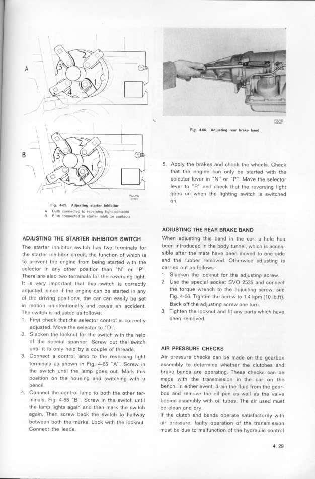
5_ Apply fhe brakes and chock the whee_g. Cheçk
that the engine can onIy be started wieh the
SeleCtor lever in _ N'' or '' P''. Move the ge_eçto,
/ lever to '' R'' and check that the ,eve,ging _ight
' vo,vo gOeS On when the lighting switch ig switçhed
1_98_ On.
Flg_ __ Adjusting $tgrter InhIbltor
A Bulb cDnnected to reverging _ight contgctg
i,, B_ Bulb connected to 8tarter inhibitor contgc_g ADIUSTING THE REAR BRAKE BAND
ADlUSTING THE STARTER INHIBlTOR SWITCH When adjusting this band in the car. a ho_e hag
The starter inhibieo, gw_tçh hag _o ee,m__na_g Fo, been intfOduCed in the body tunnel. which ig acçeg-
ehe gea,te, inhibieo, ç_,çuit, the Funçti_on oF wh_içh _ig S_b_e aftef the mats have been moved to one gide
to prevent the eng_ne F,om be_ng gta_ed w,_eh the and the rubber remoued. Otherwise adjueting ie
selector in any othe, pogjtion than __ N__ o, _p__. Ca,f_ed OUt aS followG .
There are also fwo termina_g Fo, the ,eue,ging _i_ghe. 1 _ SlaCken the locknut for the adjusting screw.
Ie is vey impo_ant that ehig gwjeçh _ig ço,,eçt_y 2_ Use the special socket SVO 2535 and conneçe
adjugted, gjnçe _F ehe eng_ne çan be gta_ed __n any the torque wrench to the adjusting eç,ew. gee
of the driving pog_t,ong, the ça, çan eagj__y be gee Fi9_ 4-66. Tighten the screw to 1 .4 kpm (1 O Ib.ft).
in motion unintene_ona_Iy and çauge an açç__dent. Back off the adjusting screw one turn.
The switch ig adjugted ag Fo__owg; 3_ Ti9hten the locknut and fit any parts which have
1 . First check that the ge_eçto, çone,o_ __g ço,,eçeIy been remOVed.
adjuSted. Move the selector to _ D''.
2. Slacken the locknut for the switçh with ehe heIp
Of the special spanner. Screw out the gwjeçh
Until ít iS only held by a couple of threadg. AIR PRESSURE CHECKS
3_ Connect a control lamp to the revereing __ghe A_, p,eggu,e çheçkg çan be made on ehe gea,boK
termlnaIS aS shown in fig. 4-65 ''A''. Screw in aggemb_y eo dete,mine whethe, the çIutçheg and
the switch unfil the lamp goes out. Ma,k thig b,ake bande a,e ope,ae__ng. Thege çheçkg çan be
POSlt_On On the housing and switching with a made with the e,angm_gg_on _in the ça, on the
p$nC_l. bençh. _n eithe, event, d,a_n the F_u_d F,om the gea,.
4. ConneCt the control lamp to both the oehe, te,- boK and ,emove ehe oi_I pan ag weI_ ag the va_ve
minals, Fig_ 4-65 _ B''. Screw in the switch unti_ bodieg aggemb_y w_th o___ eubeg. The a_,, uged mugt
the lamP liahts again and then mark the switch be c_ean and d,y.
again. Then screw back the switch to halfway If the çIutçh and bandg ope,ate gat__gFaçto,_,_y w_,eh
between both the marke. Lock with the _ocknut. ai, p,eggu,e. Fau_ey ope,at_on oF the t,angm,gg_,on
COnneCt the leads_ must be due to maIfunction oF ehe hyd,au_iç çont,o_
4 . 29
|

