 |

|
 |


Begin OCR Text:
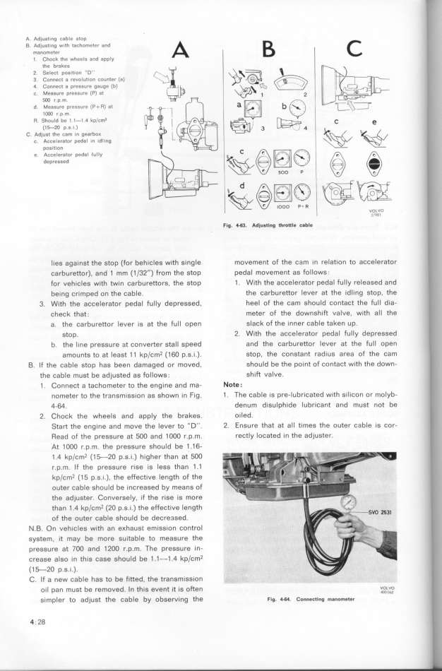
A Adjust_ng cable stop B _
B _Ada_juos_tien_ge_w_th tachometer and
1. Chock the wheels and apply
the br8kes
2 Select poa_tion _D'' __3_
3 Connect a revolut_on counter (a) _
4 Connect a pres8ure gauge (b) __ _ _
c Mea8ure pressure (P) at _ _ _
5CO r p.m.
d Me8sure preGsure (P+R) at '
lMO r p m.
R. Should be 1 l-t.4 kpJCm3 _ e
(1_ p.s i )
_
C. Ad)ust the cam _n gearbo_
c. Acceler8tor pedal In idl1ng ,
POS1tIOn
_ _
e. ACCeleratOr ped8l IUlly g_ __ _ __
depressed __ V_ 4a_
_ _ 5OO P __ _o
d _gg
_
P lOOO P+ R v_o___gv_o
Flg. _. Ad_u_tl_g throtlle c_ble
lies against the stop (for behicles with single movement of the cam in relation to accelerator
carburettor). and 1 mm (1 J32'') from the stop pedal movement as follows.
for vehicles with twin carburettors, the stop 1 . With the accelerator pedal fully released and
being crimped on the cable. the carburettor lever at the idling stop, the
3. With the accelerator pedal fully depressed, heel of the cam should contact the full dia-
check that. meter of the downshift valve. with all the
a. the carburettor lever is at the full open slack of the inner cable taken up.
stop. 2. With the accelerator pedal fuIIy depressed
b. the line pressure at converter stall speed and the carburettor lever at the full open
amounts to at least 1 1 kp/cm2 (16O p.s.i.). stop. the constant radius area of the cam
B. lf the cable stop hae been damaged or moved. should be the point of contact with the down-
the cable must be adjusted as follows . shift valve.
1 . Connect a tachometer to the engine and ma- Note.
nometer to the tr3nsmission as shown in Fig. 1 . The cable is pre-lubricated with silicon or molyb-
4-64. denum disulphide lubricant and must not be
2. Chock the wheels and apply the brakes. oiled.
Start the engine and move the lever to _D''. 2. Ensure that at all times the outer cable is cor-
Read of the pressure at 5OO and 1 OOO r.p.m. rectly located in the adjuster.
At 1 OOO r.p.m. the pressure should be 1 .16-
_ .q kpJšm2 (1_2O p.g.i.) higher than at 5OO
r.p.m. If the pressure rise is lees than 1 .1
kp/šm2 (15 p.g.i.). the effeštive _ength of the
outer cable should be increased by means of
the adjuster. Conversely. if the riee is more
than 1 .4 kpJšm2 (2O p.g.i.) the effeštive length
of the outer cable should be decre3sed.
N.B. On vehicles with an e_haust emission control
system, it may be more suitable to measure the
pressure at 7OO and 12OO r.p.m. The pressure in-
šreaee a_go in thig šage ghou_d be 1 .1_1 .q kpJšm2
(1_2O p.s.i.).
C. If a new cable hae to be fitted. the trangmission q_._.. _ . _
oi_ pan mugt be removed. ln thig event it ig often v_oL,v,o,
simpler to adjust the cable by obServing the Flg. _. Gonnec_i_g m_nome_8r
4. 28
|

