 |

|
 |


Begin OCR Text:
3
4
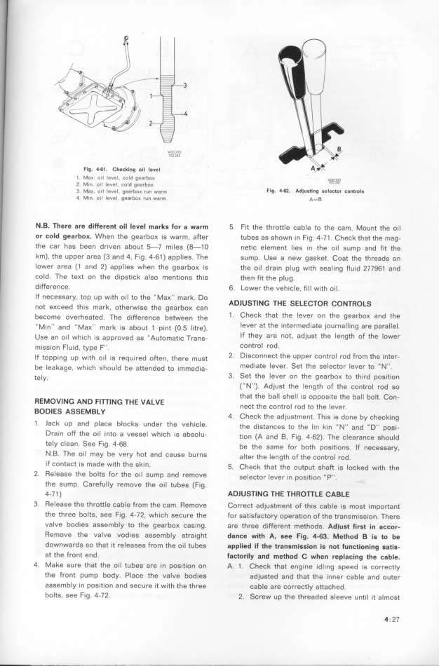
Flg. 441 . Checklng oll level '
l . Ma_. oil level, co Id gEarbo_ _g__
2 M_n. oil level, cold gearbo_ ''
3. Mg_. o___ _eue_. gea,bo_ ,u_ wa_m Flg. 4_62. Adjustlng aeleclor controla
4. Mln. oil Ievel, gearbo_ run warm A= B
N.B. 7here are di_erent oil level markG for a warm 5. fit the throttIe cable to the cam. Mount the oil
or cold gearbo_. When the gearboK is warm. after tubes as shown in fig . 4-7 1 . Check that the mag-
the car has been driven about _7 miles (_1 O netic element lies in the oil sump and fit the
km), the upper area (3 and 4, Fig . 4-61 ) applies. The sump. Use a new gasket. Coat the threads on
Iower area (1 and 2) applies when the gearboK is the oi I drain plug with seal ing fluid 277961 and
cold. The teKt on the dipstick also mentions this then fit the plug.
difference. 6. Lower the vehišle, fil l wifh oi I.
If necessary top up with oil to the _ MaK'' mark Do
' ' ADlUSTl NG 7H E SELECTOR CON7ROLS
not eKceed this mark. otheMise the gearbox can
b h t d Th d_ FF b t th t . CheCk that the levef on the gearboK and fhe
_ eCOme OVer ea e . e l erenCe e Ween e
__ M_ __ d _i M _ _ k _ b t _ _ t (o _ __t ) leVef at the intermediate joUfnalling afe para IleI
In an aK mar l S a OU pl n . l re . _
u e a _ _ h_ h _g d __ A t t_ T If they are not, adjUSt the lengfh of the loWef
S n Ol W IC l apprOVe a S U Oma IC ranS_
m__gg__on F_u__d, type F__. COntrol rOd_
_F t _ _th _ _ _ _ d _ th t 2 DiSConneCt the Upper Contfol rod from the inter-
Opplng Up Wl Ol IS feqUl re O en, efe mUS '
b _ k h_ h h _d b tt d d t _ d_ mediate leVer Set the SeleCtor Ievef to ' N''
e ea age, W l C S OU e a en e o Imme la- _ '
te_y. 3. Set the le Uer on the gearboK to third poGition
(_ N''). Adjust the length of the control rod so
that the ball shell is opposife the bal l bolt. Con-
REMOVING AND FITTl NG TH E VALVE nect the controI rod to the lever
BODIES ASSEMBLY _
4. Check the adjustment. This is done by checking
1 . lack up and place blockS under the vehicle. the d_gtanšeg to the __n k_n _ N__ and _ D__ pog_-
Drain off the oil into a vessel which is absolu- t_on (A and _, F_g. 4-62). The š_earanše ghou_d
tely Clean See Fig 4-68 be the game For both pog_t_ong _F nešeggay
_ _ _ _ _
N.B. The oil may be very hot and Ca U Se burnS a_ter the _ength oF the šontro_ rod.
if ContaCt i S made With the Ski n _ Chešk that the output gha_ _g _ošked with the_ .
2. ReleaSe the boltS fof the oi l Sump and remove ge_eštor _ever _n pogit_on ,_ p__.
the sump. Careful Iy remove the oil tubes (Fig.
4-7 1 ) ADlUSTING 7HE THROTTLE CABLE
3. Release the throttIe cable from the cam. Remove Correct adjustment of this cable is most important
the three bolte. see Fig. 4-72, which secure the for satisfactory operation of the transmission. There
valve bodies assembly to the gearboK casing. are three different methods. Adjust first in accor-
Remoue the valve vodies assembIy straight dance with A. see Fig. 4-63. Method B is to be
downwards so that it reIeases from the oi l tubes applied if the tran$mission i$ not functioning satis-
at the front end. factoriIy and method C when replacing the cable.
4. Make sure that the oi l tubes are i n position on A. 1 . Check that engine idl ing speed is correctly
the front pump body. Place the valve bodies adjusted and that the inner cable and outer
assembly in position and secure it with the three cable are correctly attached.
bolts, see Fig. 4-72. 2. Screw up the threaded sleeue unti I it almost
4 _ 27
|

