 |

|
 |


Begin OCR Text:
\\\ _ __ _ / //
//
1 2 _ 4_ 5 _
_ _
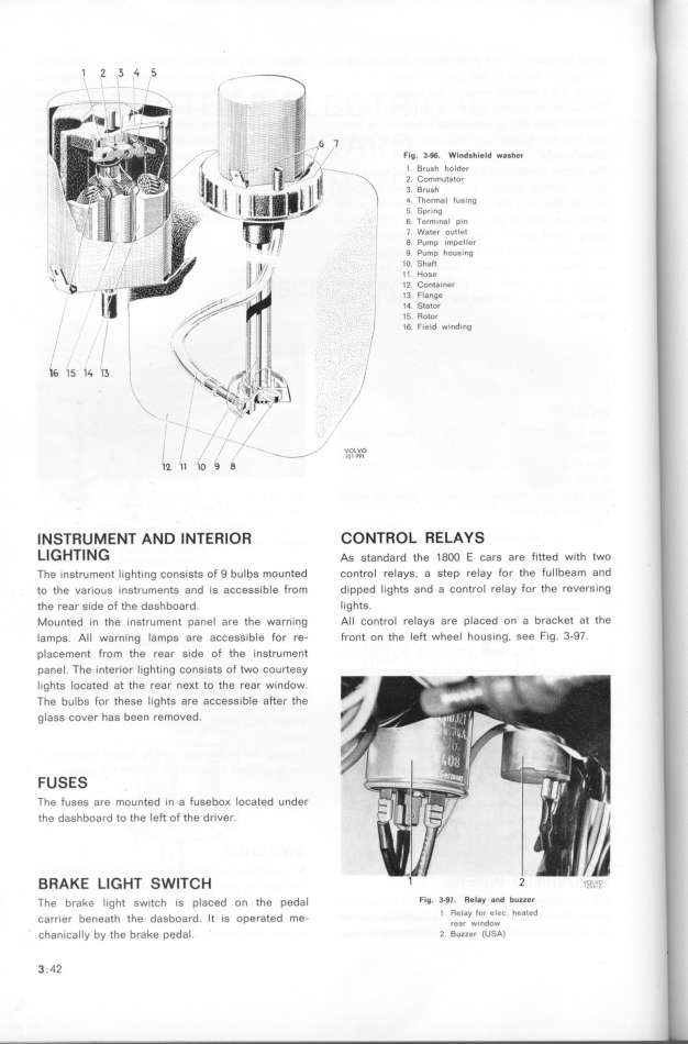
/ Fig 3_96 Wind_h_eld wa_her
__ , _
_ l Brush holder
_ h_ \ 2 Commutator
_ __ _ ) 3 Brush
_ f 4 Thermal fusing
_ _ _ Spring
6 Term_nal p_n
_ 7 Water outlet
8 Pump impeller
9 Pump housin$
_ lO Shaft
l l Hose
12 Conta_ner
13 Flange
_ 14 Stator
' _ 15 Rotor
_ .- /
16 F_eld winding
_ _ ''_ __
6 15 14 1_ h__ _
Il''_ 11 1O/ 9 8 __ _IOOIL9_9)OI
l N ST RU M E NT AN D l NTE Rl O R CO NTROL RE LAYS
Ll G HTl N G As standard the 1 8oo E cars are r_tted w_th two
The _nstrument l _ghti ng consists of 9 bu Ibs mounfed control relays. a step relay for the ful Ibeam and
to the var_ous _nstruments and _s acCess_ble from dipped lights and a control relay for the revers_ng
the rear s_de of the dashboard lights
Mounted in the _nstrument panel are the warn_ng All control relays are placed on a bracket at the
lamps Al l warning lamps are accessible for re- front on the left wheel housing, see fig 3-97
placement from the rear s_de of the instrument
panel The _nter_or l ighting consists of two courtesy
l _ghts located at fhe rear neKt to the rear w_ndow
The bulbs for these lights are accessible after the
glass cover has been removed
FU S ES
The fuses are mounted in a fuseboK located under
the dashboard to the left of the driver
_ RA KE Ll G HT SWlTC H 1 2 v?,_,_c_
The brake _ ight sw_tçh _s p_açed on the peda_ Flg_ 3_$7_ Relay and bUZZe_
carr_er benea_h the dagboard _t _s operated me- l Relay for elec heated
rear window
chanically by the brake pedal 2 _uzzer (usA)
3 . 42
|

