 |

|
 |


Begin OCR Text:
_
O II
l
1 _
2
_
4
f _
_ l_
Vol VfI 1l_
IOl l39 __
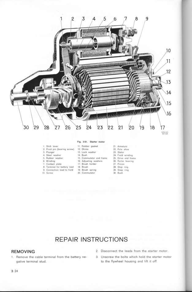
Fig. 3_5l. Starter motor li
l Shift lever Il Rubber gasket 2l. Armature
2. Pivot pin (bearing screw) 12 Shims 22. Pole shoe i
3. Plunger 13 Lock washer 23. Stator _
4 Sleel washer l4. Bush 24. field winding
5 Rubber washer 1f. Commutator end frame 2f. Drive end Irame
6. Winding 16. Adjusting washers 26. Roller bearing '
7. _ontact plate 17. Brush holder 21. Pinion
8. Terminal for battey lead l8. Brush 28 Stop ring
9 Connection lead to field 19 BJush spring 29. Snap ring
IO Screw 2O. Commutator 3O. Bush
R E PA l R I N ST R U _Tl O N S
_E_OV___ 2. Disconnect the leads from the starter motor.
1 . Remoue the cable terminal from the battery ne- 3. Unscrew the bolts which hold the starter motor
gative terminaI stud. to the flywheel housing and lift it off.
3. 24
|

