 |

|
 |


Begin OCR Text:
3 _
C
_I1_ F
11 2.
__A_ _l03OLBv_O
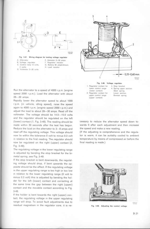
Flg_ 3__7_ Wiri,g dlagr8m _or teatl,g _olt8ge regul$tor
A Alternator E. Amme_e_ _5O ampg
B Volt8ge regulator f Regulator re8_stor
C Control lamp 12 volts, G Battey 6O amp_rehours
2 watts H Load resistor
D. Voltmeter C-2O volts _O mm
VIG3OL6,fO_
Flg. 3_. VDl_ge regulator
1 Regulator cDnt8ct for 3 Stop bracke(
R h _ d F ( lower control range 4 Spring upper sect_on.
Un t e a ternator to a Spee o 4OOO f.p.m. engine (_ower contact) _iee_ gpr,ng
gpeed 2ooo r.p m ) _oad the a_ternator w__th about 2 Regulator contact for Lower sectIon
2_ ' ' ' upper control range Bimetal 8pr_ng
3O amPs. (upper contact)
Rapidly lower the aIternator speed to about 1OOO
r.p.m. (_n vehicle. idling speed). raise the speed
again to 4OOO r.p.m. (engine speed 2OOO r.p.m.) and
adjust the load to about 28-3O amps. Read off the
voltmeter. The voltage should be 14.O-15.O volts
and the regulator should be regulated on the left
(lower) contact (1 , Fig. 3_48). The reading ghould be CeSSay to reduce the alternator speed down to_
made within 3O seconds after the test haS begun. wards O after each adjustment and then increase
Reduce the lo3d on the alternator to 3-0 ampS and the speed and make a new reading.
read off the regulating voItage. This voltage ghould (lf the adjusting is comprehensive and the regula-
now lie within the tolerance O volt to mjnue O.3 vo_t tof iS Wafm. it Can be suitably cooled to ambient
in relation to the first reading. The regulator ghould temPerature by means of compressed air before the
now be regulated on the right (upper) contact (2, final reading is made.)
fig. 3-48).
, The regulating volfage in the lower regulating range
iS adjusted by bending the stop bracket for the bi-
metal spring. see Fig. 3_49.
If the stop bracket is bent downwards, the regu_at-
ing voltage should drop. if bent upwards the op-
Posite should be the effect. If the regulating voltage
in the upper regulating range is too high or too low
in relation to the lower regulating range (O volt to
minus O.3 volt) this is adjusted by bending the hol-
der for the left (lower) contact and correcting at
the same time the gap between the right (upper)
ContaCt and the movable contact acCording to Fig.
3-48.
lf the holder is bent towards the right (upper) con-
tact, the regulat_ng voltage in the upper regulating
range will drop. To avoid fault adjustments due to v,,u,,,,,
reSidual magnetism in the regulator Core, it ig ne- Fig. __. Ad__,,_i,g __, _o,_,oi ,oit$g, '' '
3; 21
|

