 |

|
 |


Begin OCR Text:
_he negative diode holder is not isolated and ItS
d_odeg are marked in blaCk_
REp_A_lNG THE BEARINGS
Dff_vE END SHIELD BEARING
Removing
_ p_açe the rotor _n a v_se w_th soft)awS
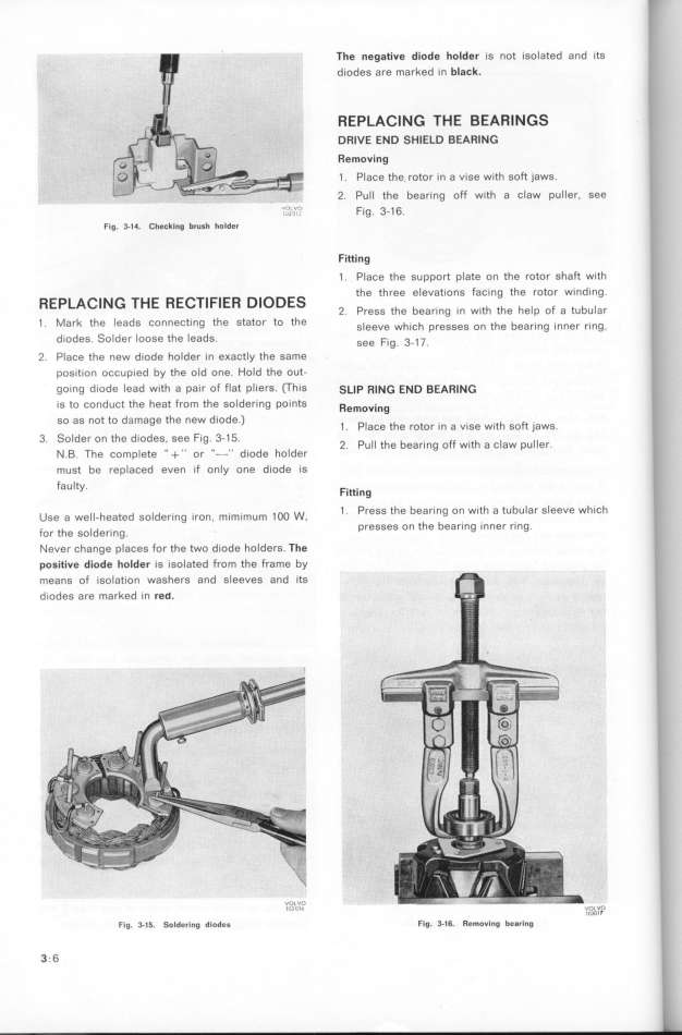
_ Pull the bearing off with a claw Puller_ See
'_,, ; fig 3_16.
F,g 3_l4. _heekl,g brUgh hOlde, Fifling
_ p_açe the support pIate on the rotor Shaft Wlth
ES the three elevations fac_ng the rotor Wlndlng
REp_A_lNG THE RE_TIFIER DlOD h b _ th th h _ F t,b _,,
2 Press t e ear_ng in w_ e e P O a U
_ _ark the leads connect_ng the stator to the ,_,,ve wh_çh preg,eg on the bear_ng _nner r_ng,
d_odes _older loose the leads see F_g 3-_ _
_ P_açe the new diode holder _n e_aCtly the Same
pog_t_on oççupied by the old one Hold the OUt-
go_ng d_ode lead with a pa_r of flat pliers (ThIS SLIP RING END BEARING
_g to çonduçt the heat from the Solderlng pOlntS ff _ g
emOVln
so as not to damage the new diode ) _ p_ th t _ th go_t )_aws
açe e ro or _n a viSe wi
3 _older on the d_odes see Fig 3-15 _ p __ h b ff th ç_aw pu__er
_ u t e ear_ng o Wl a
_ _ The çomp_ete _ + '' or ''_'' diode holder
must be replaced even if only one d_Ode IS
faulty F_tt_
l Ing
oo w 1 presg the bear_ng on w_th a tubular sleeve whICh
use a we__-heated soldering _ron, m_mimum 1 , presses on the bearing _nner rln9
for the soldering
_ever çhange plaçeg for the two diode holders The
po6jtive diode holder is _solated from the frame by
meang of _so_at_on waShefS and SleeVeS and ItS
d_odes are marked ìn red_
F,g. 3.j_. go_de,_,,g d,odeg '''U'' Flg. 3_l6. Re_O_,,0 beBr,ll0 ''3'''
3 6
|

