 |

|
 |


Begin OCR Text:
d 3 3
The isolation diode (2, Fig. 3-2) placed on the out- The alternator is self-limiting (maK. 35 amps.) and
Side of the alternator h3g two funCtiong_ it aCtg ag fof thig reason a gimple voJtage regulator Can be.
an eKtra CUt out CUrrent proteCtion fof the alterna used with on_y voltage Contro_ Thefe are two- - .
tof ShoUld any of the SiK feCtifief diodeS Stop fUnC- types of voltage fegulatof available. Ful_y trans_
tioning; and _t makes simple connecting up of the istorized and mechanical.
WafnIng Chafg_ng lamp pOSSlb_e.
_ EPAl _ l __T_ U_Tl O__
_Po
E_K
IAo
L INSTi
RU_N
TlOo
NS FE
Oij
R p
DISMANTLIN_ THE ALTERNATOR
W R N AL ER AT R Ul _ _ Re_eage the two gšrews ho_d_ng the brugh ho__E_i . =
der and remove the 'golat_on p_ate _ __ out fheI . U
1. When replašing or fitting the battery, make SUre brugh ho_der.
that the neW battefy iS COnneCted With the COf_ 2 F the p __ y w th b _t _ _th _)a. IK U e I e In a vISe Wl SO WS.
reCt pOlar_ty see fi_ 3 6
_ _. - .
2 NeVef rUn the alternatOr With the main CirCU_t 3 R mo th n t d a h __Ft FF th p ___ . e ve e U an w S ef. i o e u ey,
broken The battery and/or alternator and regu- F k d h
_ an, ey an SpaCer WaS er.
Iafor leadg mUSt never be digConneCted While R h d
4. emove t e nuts an washers on terminal 61
the engine ig running d h h F
' an t e corresponding on t e other side o the
3 No attempt ShoUld be made to polafiZe the al_ _ _ f_ d d _ _ FF th _ _ t d d h _
_ iso a ion _o e. i o e iso a ion Ýo e o -
ternator since this is not neceesay d _ F_ 3 _
_ er. ee Ig - .
4 When Charging the b3ttery Whlle _nStalled in the _ _ fk th d _ e d gh_ _d t t d s_
_ . a e riv en ie , s a or an ip ring
VehiCle thg gfoUnd battery lead ShoUld be d_S_ end sh_e_d to a o_d šonF _ whe assem__
_ V I USlOn n _ -
ConneCted _ Re the F aff h C_ Ing. mOVe OUf aC Ing S reWS.
5. A rapid Charger ShouId not be uSed aS a help _n
starting.
6 When using an eKtra battery as an aid in start-
, ing, alw3yS ConneCt It in pafallel.
7. When carying out any electric weld_ng on the
vehiCle, digšonneCt the ground battery lead aS
well as all the alternator leads. The welding
unit ShoUld always be ConneCted as near 3S
poss_ble to where the wefding is to be carried
out.
_EMOV_N_ iHE <ERNAiOR
1. Disconnešt the ground Iead to the battery.
2. DigConnešt the leads to the alternatof.
3. Remove the bolt fof the adjuStment arm.
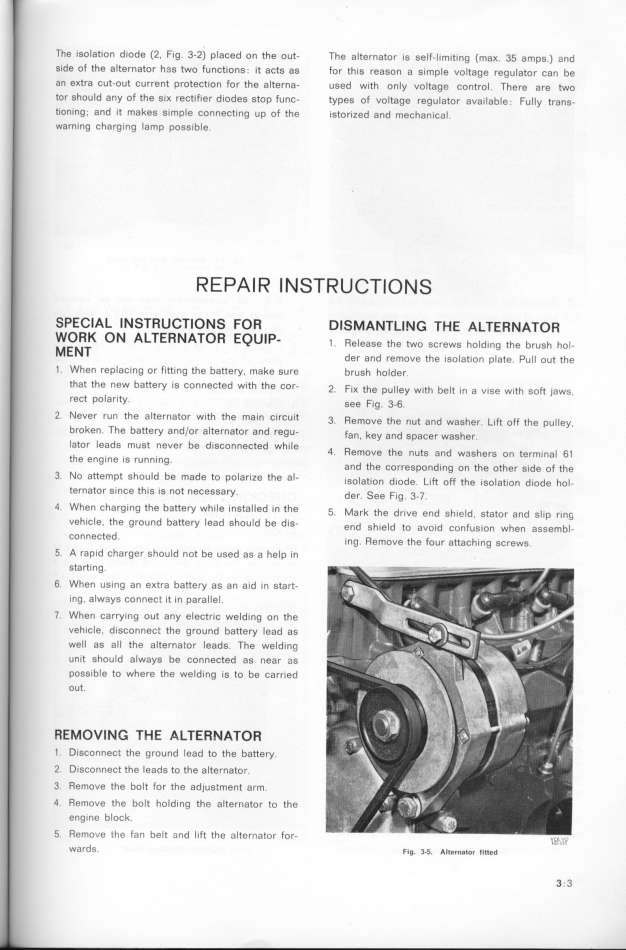
4. Remove the bolt hold_ng the alternator to the
eng_ne b_OCk.
5. RemoVe ihe fan belt 3nd lift the alternatOf fOf- _g_L_,_
|

