 |

|
 |


Begin OCR Text:
B A _ _ E _ y
GROUP 3D
_ E N E RA_
The electrical system is des_gned for a voltage of tor, starter motor, ignition system, l_ghting. other
12 V The equipment is made up of the follow_ng electr_cal standard equipment and _nstrumenfs
main parts Battery, alternator and voltage regula-
GROUP 3_
D ES_ R I __I O N
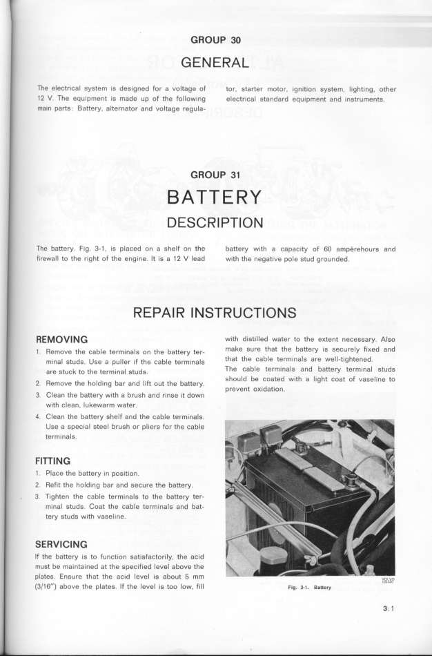
The battery Fig 3-1 , is placed on a shelf on the battery w_th a capac_ty of 6O amperehours and
f_rewall to the right of the engine lt is a 12 V lead w_th the negat_ve pole stud grounded
R E_A I R l N S_R U __l O N S
_E_OVlNG w_th distilled water to the eKtent necessay AIso
_ Remove the cab_e term_na_S on the battery ter- make sure that the battery is securely f_Ked and
m,na_ studS uSe a pu__er iF the cab_e term_na_s that the Cable termina1S are well-t_ghtened
are stuÁ_ to the term_na_ StudS The Cable termlnaIS and battery tefmlnal StUdS
should be coated w_fh a l_ght coat of vaseline to
2 Remove the holding bar and lift out the battery prevent oKidation
3 Clean the battery w_th a brush and rinse _t down
with clean. Iukewarm water
4 Clean the battery shelf and the cable terminals
Use a special steel brush or pliers for the cable
terminals
FITTlNG
1 Place the battery in position
2 Refit the hold_ng bar and secure the battery
3 T_ghten the cable terminals to the battey ter-
mina_ studs Coat the cable term_nals and bat-
tery studs w_th vaset_ne
SERVICING
If the battery _s to function sat_sfactorily, the ac_d
must be ma_ntained at the specified level above the
plateS EnSure that the aCid level iS abOUt 5 mm _,,_,_,_,_,
(3/16'') above the plates If the level _s too low. f_ll F_g. 3-1. Ba__ery 3 1
|

