|

|
 |


Begin OCR Text:
_ _
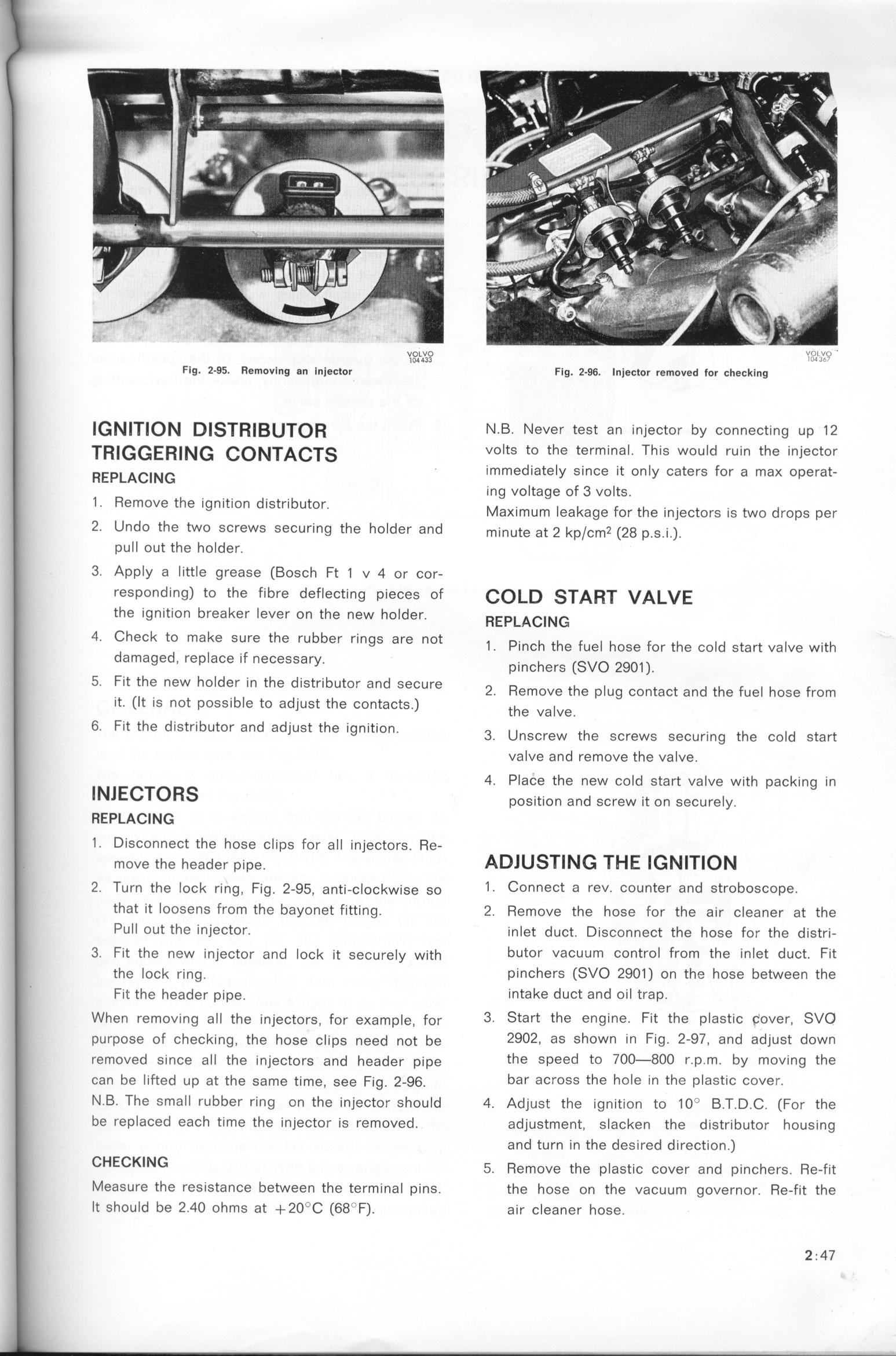
Flg. 2_$5. RemovIng an Injector vlOD'L'''O3 Flg. 2-96. Iniector removed _or checking '''''-'''''_'_'
JGMJTJOM DJSTRJ_UTOR N.B. Never test an injector by connecting uP 12
TR_GGER_N_ CoNTACTS volts to the terminal. ThiS wouId ruin the injector
RepLAC___ _ immediately since it only caters for a ma_ operat_
ing voltage of 3 volts.
1 Remove the ignition distributor M _ k F h d
' _ a_imum ea age or f e injectors is two rops per
2. Undo the two sCrewS SeCUring the holder and minute at _ kp/þm2 (2g p.S._.).
puIl out the holder.
3. Apply a little grease (Bosch Ft 1 v 4 or cor-
resPonding) to the fibre deffecting pieces of CO_D START VA_VE
the ignition breaher lever on the new hoIder. REpLAC__G
4 Check to make sure the rubber rings are not p h h F _ h F h _d _ h
' 1 . inc t e ue ose or t e co start va ve wit
damaged replace if necessary h (Svo 2go )
' _ plnC erS 1 .
5 fit the new holder 1n the distributor and secure _ h _ d h F h F
' 2. emove t e p ug contact an t e uel ose rom
it (lt is not possib7e to adjust the contacts ) h _
' ' t e Va Ve.
6 fit the distributor and adjust the ignition u h h _d
' ' 3. nscrew t e screws securing t e co start
valve and remove the valve.
4. PIace the new cold start valve with packing in
INlECTORS poS_EUR_on and Sþrew _t on Seþure_y.
REPLACING
1 . Disconnect the hose clips for all injectors. Re-
move the header p_pe. ADJUSTING T_E IGNITlOM
2. Turn the _oþk ring, Fig. 2-g_. anti-þ_oþkwjSe So 1 . Connect a rev. Counfer and StroboSCope_
that it loosens from the bayonet fitting. 2. Remove the hose for the air cleaner at the
Pull out the injector. inlet duct. Disconnect the hose for the distri-
3. fiEUR the new _n)eþtor and _oþk jEUR Seþure_y w_EURh butor vacuum control from the inIef duct. Fit
the _oþk ring. pinChefS (SVO 29O1) on the hoSe between the
' Fit the header pipe. intake dUCt and Oil trap.
When remou_ng a__ the injeþEURorS. For e_amp_e. For 3. Start the engine. fit the plastic c. over, SVO
purpoSe oF þheþking, EURhe hoSe þ__pS need not be 29O2, as shown in Fig. 2_97, and adjust dOwn
re_oved Sinþe a__ the _njeþEURorS and header pjpe the speed to 7OO-8OO r.p.m. by moving the
þan be _ifEURed up at the Same time, See Fjg. 2-g6. bar across the hole in the plastic cover.
N.B. The small rL_bber ring on the injector should 4. Adjust the ignition to 1 O' B.T.D.C. (for the
be replaced each time the injector is removed. adjustment, slacken the distributor housing
and turn in the desired directýon.)
CHECKING _. Remove the p_astic cover and p_nchers. Re-rit
Measure the resistance between the terminal pins. the hose on the vacuum governor. Re_fit the
It should be 2.4O ohms at +2O''C (68_ f). air cleaner hose. 2.47
|