 |

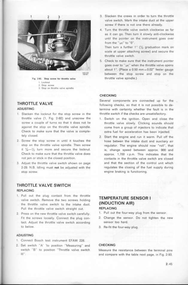
|
 |


Begin OCR Text:
_ _ 3 _ 3. Slacken the crews in order to turn the throttle
valve switch. Mark the intake duct at the upper
screw if there is not one there already.
4. Turn the throttle valve switch clockwise as far
as it can go. Then turn it slowly anti-clockwise
until the pointer on the instrument goes over
from the ''oo'' to ''O''.
7hen EURurn a further 1 O (1/j graduaEURion mark on
scale at upper attaching screw) and secure the
throttle valve switch.
5. Check to make sure that the instrument pointer
goes over to ''oo'' when the throttle valve opens
about 1 '. (Place a O.5O mm = O.O2'' feeler gauge
UOLUO b _ th t d t th
__43l e een e g Op gšreW an g Op On e
Fig. __9_. Stop a_rew _or t_ro_Ie _aIve throttle valve spindle.)
l Locknut
2. Stop screw
3. Stop on throttle valve spindle CHECKING
THRoTT_e vA_vE Several components are connected up for the
following checks. so that it is not possible to de-
ADlUS7lNG EURermine with šertajnty whether the fau_t is in the
1 . Slacken the locknut for the stop screw in the throttle switch if the checks are unsatisfactory.
throttle valve (1 , Fig. 2-92) and unSCfew the 1 . SwjEURšh on the jgnition. Open and š_oge the
sCrew a couple of turns so that it does not lie thrott_e va_ve g_ow_y. C_jškjng goundg ghou_d
againSt the Stop on the throttle Valve Spindle. šome from a group of inještorg to indišate that
CheCk tO make sure that the valve is CompIe- eKtra fue_ for ašše_eration hag been inješted.
tely ClOSed. 2. _EURart the eng__ne and run __t warm. pu__ oFF the
2. Screw the stop screw in until it touches the hoge beewen the jntake dušt and auK___ary a_r
stOp on the throttle value spindle. Then sCrew regu_ator. 7he engine ghou_d now _ro____, EURhat
it 1/_-1/z turn mofe and SeCure the loCknut_ ig, šhange gpeed between approK. goo and
Chech to mahe sure that the throttle vatve does approK. _ ,_oo r.p.m. Thig _ndjšateg that the
nOt jam Or stiCk in the ClOSed pOSition. šontaštg in the thrott_e va_ve gwitšh are š_oged
3. Adjust the throttle valve switch shown on page and that the section of the control unit which
2-29. N.B. ldling must not be adjusted with the regulates the closing of the fuel supply during
stop screw. engine braking is functioning.
THROTTLE VALVE SWITCH
REPLACING
1 . Pull out the plug contact from the throttle TE_pERATuRE Se_SoR _
valve switch. Remove the two screws holding i__ij C o
EURhe thrott_e va_ve gw_tšh to the _ntake dušt. U Tl N AIR_
Pull the throttle valve switch straight out. ffEPLACING
_. pregg on EURhe new thrott_e va_ve gw_EURšh šareFu__y. 1 . Pull out the four-way plug from the sensor.
fit the screws loosely. Connect the plug con- 2. Change the sensor. Do not tighten the new
tact. Adjust the throttle valve switch according sensor too hard. '
to below. 3. Re_fit the four-way p_ug.
ADlUS7lNG
1 . Connect Bosch test instrument EfAW 228.
2. Set switch ''A' 'EURo position ''Measuring'_ and CHECHING
switch ''B'' to position ''Throttle valve switch Measure the regigEURanše between the termina_ ping
Ill''_ and compare with the table neKt page, in Fig. 2-93.
2._45
|

