 |

|
 |


Begin OCR Text:
)
__ _____o _ order to provide a smooth changeover to id ling
' V _ V ' V F _ F h speed If the engine does not reach a sPeed of
Fue_ i S draWn by the e_eCtrIC Ue PU mp rOm t e ' oo b F b k. t t
k h h th F _t F h .t d apprOK. 1 7 r.p.m_ e Ore engl ne r3 l n9 S ar SI
tan t ro Ug e l er fOm W ere l IS COnVeye
h F _ _ thg FUe_ IS ShUt OFF.
under pressure _ntO t e ue _ ne.
The preggure regulator. which is con nected to the /
end oF the pressure _ _ ne, I imits the fue I pressure ,, __
to 2 kp/cm2 (28 p.s.1 ) EKcess fuel from the pres-
sure regulator flows back to the tank through the
return li ne. The electro_magnetic fuel injectorS, /_
which are mounted in the intake ports i n the cyl in-
-
der head , are connected to the fuel l ine. - -
The durat_on of injection for the i njeCtors is goVern-
ed basically by engi ne load and speed .
The pregsure sensor senses the absolute pressure
i n the _ n_et duct and converts it to eleCtri Cal im- -
pulses which are processed by the control unit.
_i nce the pressure _n the i nlet duct is proporfional -
to engine load. the control unit receives i nforma- , ' , ,
t_on concerning the engine load in this way. _ _ / _
The triggering contacts in the distributor provide \ý _
the control unit with i nformation aboLit the engi ne
speed.
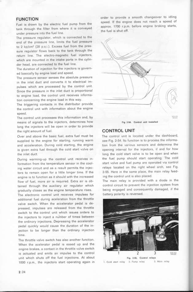
The control u nit processes this i nformation and. by _'_,. __''
means of signals to the i njectors, determines hOW F_g _._. con_roi un_t Instaiied
long the injectors wi Il be open i n order to provide
the r_ght amount of fuel . _ O ___O _ U _ __
Over and above the basic fuel , eKtra fuel must be The control un it is located under the dashboard,
su ppl _ed to the engi ne for starting , running warm gee fig. 2-54. Itg function is to process the i nforma-
and accelerat_on. During cold Sta_ing, the engi ne tion from the variou__ sensors and determ _ne the
is given eKtra fuel through the cold start valve on open ing interva_ for the inještors, _( and for how
the i nlet duct. _ong the cold start valve is to be open and when
During warmi ng-up the control unit receives i n- the fuel pump should start operating_ The cold
formation from the temperatu re gensor in the šoo_- staft valve and Fuel pump afe opefated Via ContfOl
ing water c_rcu _t and as a result permits the injec- relays located on the rig ht wheel arch, See fÝg_
torg to rema_ n open for a _itt_e longer ti me. _f the 2-55. Here in the n_ame place, the mai n felay feed-
engi ne is to function as it should with the increased i ng the control un it is also Placed ,
flow of fuel. more air is required. EKtra ai r is ob- The ma_n relay _s provIded with a d iode in the
tained through the auKi liary air regu lator which control circu _t to prevent the injection SyStem ffom
gradua I Iy closes as the engine temperature rises. being engaged and conse4 uently damaged , if the
The eleštronic control unit receives impulses for battery polarity is reversed_
addit_onal fuel during aceleration from the throttle
valve switch. When the accelerator pedal is de-
presn_ed, i mpulses are released from the throttle
switch to the control unit which i Ssues orders to
the in3ectors to inject a number of times between
the ord in3ry i njections. Depressing the accelerator _
pedal quichly wou Id cause the durat_on of the i n-
jection to be longer than the ordinary injection '
t_me.
The throttle valve sw_tch has also another function.
When the acelerator pedal is eased u p and the ,
eng ine brahes. a contact in the throttle v_lve switch ,
is actuated and emits an i mpulse to the control _ 2 3 ,,o,L,_,_ l,
unit which shuts off the fuel injections. At about F_g. _.__. cont_o_ reiays !
_ OOO r.p.m.. the i nještorg sta_ opgrati ng again in t _old start relay 2 Pump rclay 3 Main rclay _,.
2 . 24 _.
|

