 |

|
 |


Begin OCR Text:
f
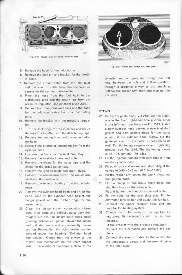
Flg. 2_l9. Gulde pl_s for tltIlng _yll_de_ head . . . . . .
P___
Flg. 2-2O. Valve se8t wldth A=2 mm (O.O8')
5. Remove the hose for the induction air.
6. Remove the lock pin and bracket for the thrott-
Ie šable. cylinder head oil goes up through the bolt
7. Remove the ground cable from the inlet duct hole, between the bolt and hollow partition.
and the electric cable from the temperature through a diagonal oilway to the attaching
sensor for the coolant thermometer. bolt for the rocker arm shaft and then up into
8. Pinch the hose from the fuel tank to the the shaft.
distributing pipe and the return line from the
pressure regulator. Use pinchers SVO 29O1 .
9. Remove both the pressure hoses and the hose
for the šo_d gfarf va_ve From the d_gtr__b,t_ng FlTTING
pipe. 22. Screw the guide pins SVO 2435 into the block.
1 O. Remove the bracket with the pressure regula- one in the front right-hand hole and the other
tor. in the left-hand rear hole, see fig. 2-19. Install
1 1 . Turn the lock rings for the injectors and lift up a new cylinder head gasket, a new inlet duct
the injectors together with the dietributing pipe. gasket and new sealing rings for the water
12. Remove the heating hose and the upper radia- pump. Fit the cylinder head. Screw out the
tor hose. guide pins and fit the bolts in these holes as
13. Remove the alternator tensioning bar from the well. for tightening sequences and tightening
cylinder he3d. torques. see fig. 2-16. The tightening torque
14. Unscrew the bolts for the inlet duct stay. is 8._9.5 kpm (6_7O lb.ft.).
1f. Remove the inlet duct nuts and bolts. 23. fit the injector holders with new rubber ringe
16. Remove the clamp for the water pipe and the on the cylinder he3d.
clamp for the brake servo hose. 24. Fit push rods and rocker arm shaft. Adjust the
1 7. Remove the ignition le3ds and spark plugs. valves to O.4O-O.45 mm (O.O16-O.O18'').
18. Remove the rocker arm cover. the rocker arm 25. fit the rocker arm cover, the spark plugs and
shaft and the push rods. the ignition leads.
19. Remove the injector holders from the cylinder 26. fit the clamp for the brake seruo hose and
head . also the clamp for the water pipe.
2O. Remove the Cylinder head bolts and lift off the fit and tighten the inlet duct nuts and bolts.
head. Take off the cylinder head gasket, the 27. fil the bolts for the inlet duct stay. fit the
flange gasket and the rubber rings for the alternator tension bar and adjust the fan balt.
water pump. 28. Connect lhe upper radiator hose and the
21 . Clean the piston crown, combustion cham- hose for the heating system.
bers, inlet ports cnd eKhaust ports very tho- 29. Change the rubber seals on the injectors for
roughly. Do not use emery cloth since small new ones. fit the injectors with the distribut_
grinding particles can get in between the piston ing pipe.
and cylinder walls and consequently cause Fit the brachet with the pressure regulator.
scoring. Recondition the volve system as de- Connect the fuel hoses and remove fhe pin-
scribed under the heading _Cylinder head chers.
and valves''. Check that the oilway to the 3O. Connect the electric cable to the sensor for
rocker arm mechanism on the ualve tappet the temper3ture gauge and the ground cable
side in the middle of fhe head is clean. _n the to the inlet duct.
2; 1 O
|

