 |

|
 |


Begin OCR Text:
P 18OO
The heater, which is illustrated in Fíg. 18, consist
of the foIlowing main parts. fan housing with fan
wheel and electric motor, cell system, distribution
housing ~ncluding shutters, heat_r control vaIve
and controls.
The figure also shows the dírection of air flow.
HEA_ER CON_ROL VALVE
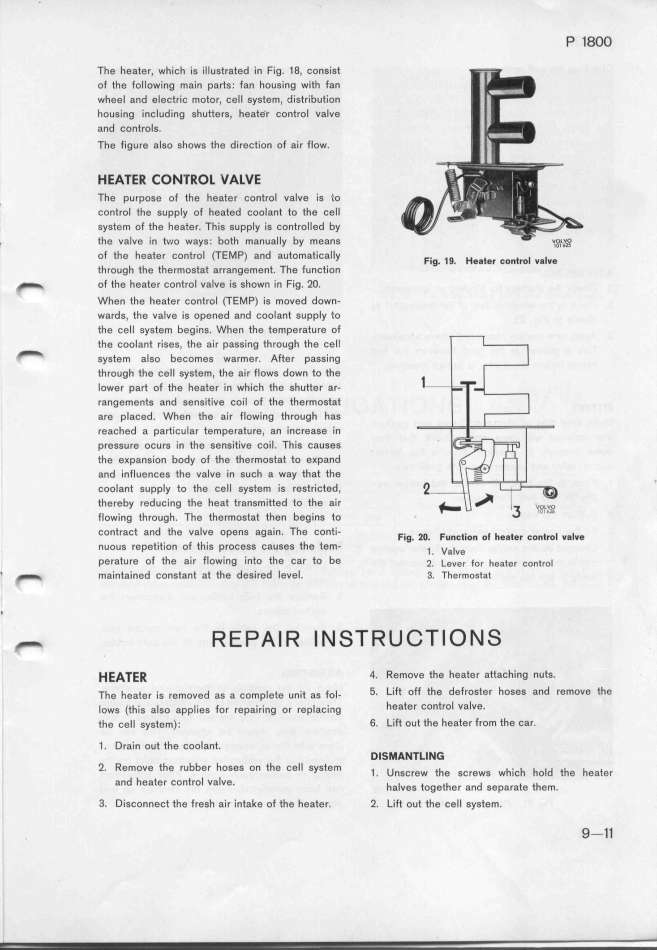
, The purpose of the heater control valve is _io
Control the supply of heated coolant to the cell
system of the heater. This supply is controIled by
_ the vaIve in t_*Io ways. both manually by means ,,,,,,
of the heater control (TEMP) and automatically F.,g _g H,,_, , _ _ _
through the thermostat arrangement. The function ' ' ' '' '' '' ''
_ of the heater control valve is shown in Fig. 2O.
When the heater control (TEMP) is moved down-
wards, the valve is opened and coolant suppIy qo
the cell system begins. When the temperature of
the coolant rises, the air passing through the ceIl
_ system also becomes warmer. After pass_ing
through the cell system, the air flows down to the
Iower part of the heater in which the shutter ar-
rangements and sensitive coil of the thermostat
are placed. When the air flowing through has
reached a particular temperature, an increase in
preSsure ocurs in the sensitive coil. This causes
the expansion body of the thermostat to expand
and influences the valve in such a way that the
coolant supply to the cell system is restricted,
thereby reducing the heat transmitted to the air
flowing through. The thermostat then begins to
contract and the vaIve opens again. The conti- F.,g _o F,,,_.,o, o_ _,,_e, ,, _ _ _
nuous repetition of this process causes the tem- ' _ va_,, ' '' '' ''
perature of the aír flowing into the car to be _' i,,e, f,, _,,_,, ,,,_,,_
' _ maintaìned constant at the desired level. 3_. __e,_o__,_
' _ R E p A _ R _ N s T R u c T _ o N s
HEA_ER 4. Remove the heater attaching nuts.
The heater is removed as a complete unit as fol- 5_ Lift off the defroster hoses and remove the
Iows (this also applies for repairing or repIacing heater controI valve.
the cell system); 6. Lift out the heater from the car.
1 . Drain out the coolant. DISMAN7LING
2_ RemOVe the fUbbef hOses on the ceIl system _ unscrew the screws wh.ch h ld th h t
and heater control vaIve. ' haives together and separlate thOem e ea ef
3. Disconnect the fresh air intake of the heater. 2. Life out the cell system. '
_ 9-11
|

