 |

|
 |


Begin OCR Text:
P _ 2O, P l 8OO _ E _ A _ _ l N 5 T _ U _ T l O N 5
CHECKING 7HE SHOCK ABSORBERS
A simple woy of checking the condition of the
shock obsorbers is to rock the cor up ond down
and then releose it. when the domping effect of
the shock obsorbers con be observed. Testing con
olso be corried out by driving the vehicle over
o bumpy rood surfoce.
If the shock obsorber hos been removed from the
veh_icle, the lower ottochment shouId be tigftly
cIomped in o position similor to tfot when fitted
on fhe vehicle. IF 'it is then quickly pulled out ond
compressed olternately, it is possible to iudge _
whether it is operoting ot oll. However. the
domping eFfect con only deFinitely be decided
witf the help oF speciol test devices.
When checking shock obsorbers, note thot the
resistonce when pulling out is normolly obout _
three times greoter thon when compressing due j j j i i
d __D9_
to its es'ign.
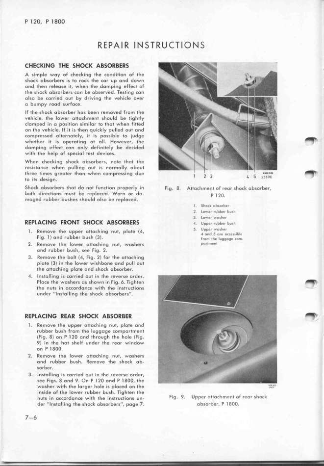
Shock obsorbers thot do not Function properly in Fig. 8. Attochment of reor shock absorber,
both directions must be reploced. Worn or do- p _ 2o.
moged rubber bushes should olso be replaced. _. 5fock obsorber
2. lower rubber bush
o 3. lower wosher
REPtACING FRON7 SHOCK ABS RBERS _ upper rubbe, bush
_ R h tt h_ t i t (_ 5. Upper wosher
. emoVe t e Uppef o OC In0 nU , p O e , 4 o_d _ o_e o__egg_b_e
Fig. l ) ond rubber bush (33. _ro_ ihe _uggoge co_.
2. Remove the lower ottoching nut. woshers P''t_''t
ond rubber bush, see Fig. Z.
3. Remove the bolt (4, Fig. 2) For the ottoch_ing
plote (3) in the lower wishbone ond pull out
the ottoching plote and shock obsorber.
4. Instolling is corried out in the reverse order.
Ploce ffe woshers os shown in Fig. 6. Tighten
_
the nuts in occordonce with the instructions -
under ''Instolling the shock obsorbers''.
REPlACING REAR SHOCK ABSORBER _'
l . Remove the upper ottoching nut, plote ond
rubber bush from the luggoge comportment
(Fig. 8) on P l 2O ond througf the hole (Fig.
_) in the hQt sheIF under the reor window
on P l 8OO.
2. Remove the lower ottoching nut. woshers
ond rubber bush. Remove the sfock ob-
sorber.
3. InstoIIing is corried out in the reverse order,
see Figs. 8 ond _. On P l 2O ond P l 8OO, the
wosher wifh the Iorger hole is placed on the '.___'i_'
inside oF the lower rubber busf. Tighten the
nuts _in occordonce w__th the _,nstruct_,ons un- Fig. _. Upper ottochment oF reor shock
der ''_nsto_iing the shock obsorbers''. poge _. Qbsorber. P l 8OO.
7-6
|

