 |

|
 |


Begin OCR Text:
_
P _ 2 O, P _ 8 OO
_,i z_ 3_ __
5 6__ 1j g_ g lO_
_3 zz z_ zo )g )g I_ _6 )f I_ l3 l2 ,Dl,,I_
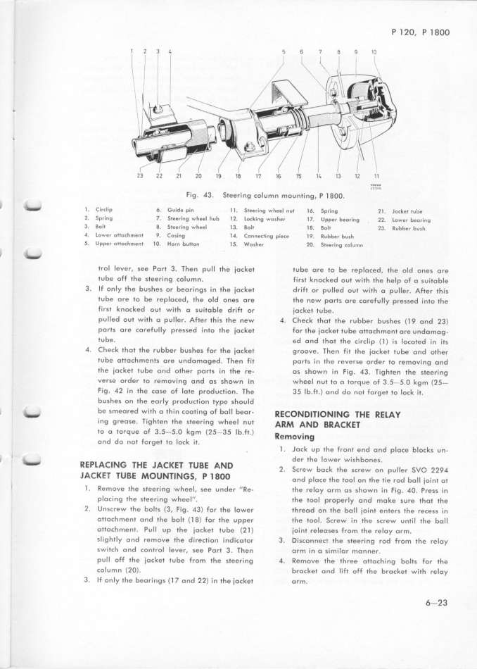
Fig. 43. Steering col um n mounti ng. P l 8OO. _'M'
_ _ ) _ _ 6 _ _d _ ) ) __ _ _ ) )6 _ z) _ _ ) ) b. _rc _p . ui e pin . eering W pp nu pring oc e u e
2. Spring J Steering wh8el hub l 2. lo_king wo_her l J Upper beoring 22 Lownr b8oring
3 Bolt 8 5t88ring wheel l 3 Bolt l 8. aoIt 23 Rubbpr bvIh
d lovgr oItoch_ent q _o_ing l4 _onngcling pigcg l _. _ubbgr bu_h
S Upper oitoch_enr ) O. Horn button lf Wo_her 2O Si8pring colu_n
_ _ trol lever, see Port 3. Then pull the iocket tube ore to be repIoced. the old ones ore
tube off the steering column. first knocked out with the help of a suitoble
3. If only the bushes or beorings in the jocket dri Ft or pu Iled out with o puller. AFter this
tube are to be replaced. the old ones ore the new ports ore corefully pressed i n1o 1he
fi rst knDcked out with o suitoble drift or iocket tube.
pu l Ied ou1 with o pul ler. After this the new 4. Check thot the rubber bushes ( l 9 ond 23)
ports ore coreful Iy pressed into the iocket for 1he iocket tube ottoch ment ore undomog_
tube. ed o nd thot the circlip fl ) is locoted in its
4. Check 1ho1 the rubber bushes For 1he iocket groove. Then fi I the iocket tube ond oIher
1ube ottoch ments ore undo moged. Then Fit ports i n the reverse order to removi ng ond
the jocket tube o nd other ports in the re_ os shown in Fig. 43. Tighten the steeri ng
verse order to removi ng ond os shown in wheel nut to o torque of 3. f-5. O kg M (2f-
Fig. 42 i n the cose Df lo1e production. The 35 Ib. Ft.) ond do not forget to lock it.
bushes on the eorly production type should
, _ be s Meored with o thi n cooting oF bol I beor_ ffe_oN D___o N_N_ 7He ff ElAy
_ ng g reose. Tig hten the steeri ng wheel nut AffM AND _ffA_ KE_
to o torq ue oF 3 5-f O kgm (Z5-35 Ib ft ) ff _
' ' ' _ elfloVIItg
ond do not forget to lock it. l . Jock up 1he front end ond p Ioce blocks un-
, l _ der the lower wi shbones.
REPl AC_ NG 7HE JACKE7 7UBE A ND _ _ b _ )_ _j _vo ____
. creW oc e screw on pu er
JAC KE7 7U BE MOUNTl NGS P l 8OO d _ __ ) _ )_ )_ d b j_ _ _ ) )r on p oCe e oo on e ie ro o _o_n o
_ l . Remove the steeri ng wheel, see under '' Re_ the reloy orm os shDwn i n Fig . 4O. Press in
ploci ng the steeri ng wheel''. 1he tool properly ond moke sure thot the
2. Unscrew the bolts (3. fig. 43) for the lower threod on the boll ioi nt enters the recess in
ottoch Ment ond the bolt (l 8) For the upper the tool. Screw i n the screw unti l the bol l
ottochment. Pull up the iocket tube (2 l ) ioi nt releQses from the reloy or M.
sIigftly ond rem Dve the d irection i ndicotor 3. Disconnect the steeri ng rod fro M the reloy
switch ond cDntrol lever, see Port 3. Then orm i n o similo r Man ner.
pu Il Dff 1he iocket Iu be from the steeri ng 4. Remove the 1hree ottochi ng bol1s for the
colu mn (2 O). brocke1 ond lift oFf the brocket with reloy
3. If on Iy the beorings ( l 7 ond 22) in the iocket orm. 6=23
|

