 |

|
 |


Begin OCR Text:
_
__
P 1 2O. P 1 8OO
5. 5crew out tfe Iocking screw and remove the
Ioop (1. Fig. 49) and button (2). Take out the
spring (4) Irom the lever. Remove tfe rivet (8)
and take ouf the push rod (6) and pawl (7).
6. Fit the new parts in the reverse order, see
Fig. 49. Make sure fhat the rivef is properly
secured without the movement of the pawl
being atlecfed. Lubricate fhe busfes wiIh a
thin layer ot ball bearing grease. _Do not forget
to lock the pull rod and ensure that the rubber
cover on the shBlt seals properly.
REPLtCIH_ 7HE HtHDBRtKE LE_ER OR
Rt7CHEt PtRtS, P 1BOO
_ 1. Release fhe handbrake and remove the pro-
tective couer.
, 2. Remove fhe 5piif pi, a,d wa5he_ o, fhe 5half '___i_'
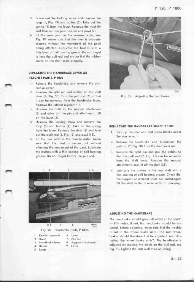
Iever C6. Fig. 5O). Turn the pull rod C7) so that Fig. 51. Adjusting the handbrake.
it can be removed trom the handbrake lever.
_ Remove fhe ratchef segmenI C1).
3. Unscrew the bolts lor the support attachment
(8) and drive out fhe pin and attachmenf. LilI
olf the lever (3).
4. Unscrew the locking screw and remove the
, loop C5) and button C4). Take oll the spring REPLtCIHG 7HE HtHDBRtKE SMtF7. P 1BOO
lrom the lever. Remove the rivet (2) and Iake _ _ k _h d d i b_ k d
. aC Up e fEaf en an p aCe OC 5 Un ef
, out the push rod (6, Fig. 13) and pawl (18). jhe ,ea, a_ie
5. Fit the new parfs in the reverse order. Make '
5u,e jhaj _he ,__vej __5 5ecu,e bu_ w_,jhouf 2. Release the handbrake and disConnect the
ajje,j,_,g jhe mov,me,j o_ jhe p,wi. L,b,_,,,fe pull rod (l. Fig. SO) lrom lhe shalt lever C6)_
tfe bushes with a tfin coating ol ball bearing 3. Remove the sptit pin and pull Ihe cables so
grease. Do nof lorget to lock the pull rod. that the pull rod (2. Fig. 13) can be removed
(rom the shaft lever. Remove the support
aftachmenfs and lift off the shalt Cl1).
_
t 2 3 4 f 4. Lub,íc_je the bushes in the new shalf witf a
_ thin coating of ball bearing grease. Check that
the support attachment studs are undamaged.
. Fit tfe shalt in the reverse order to removing.
tDlUS7lHG 7HE HtHDBRtKE
' The handbrake should give lull eftect at the fourth
g g _ 6 vo_vo - lilfh notch. Il not, Ihe handbrake should be ad-
Z_ft7 _ j d _ j d_ j_ k jh j th f bi
)Us e . e ore a )us ing, ma e 5Ure a e rOU e
Fig. 5O. Handbrake parts. P 18OO. h h i
_5 ,of In the Wheel brake UnIt5, T e feaf W ee
1. Ratchet segMent 6. Lever b,ake, 5ho,_d jhe,ejo,e j;,5j be adj_u5jed, 5ee ..Ad-
2_ Rivet 7_ Pull rod )_u5j__,g jhe whee_ b,ake un_ij5.. The handb,ake __5
3. Handbrake lever 8. 5upport attachment d. d b . jh i . ' h ii d
4. _u__on g. _eve, a jUSfe y moVing e C eviI on f e pU fO , 5ee
_. _oop Fig_ 51_ Tighten the nuts well after adjusting_
_-23
|

