 |

|
 |


Begin OCR Text:
P 1 2O. P 1 8OO
brake lIuid tuIlilling the requirements ol SAE _eakage _e__
7O R 3_ Fluid which only tultils the require_ o,,e o, iw_,,e , yea,. ,,d wfe, ,,y fyd,gu__,, ,om_
ments ol 5AE 7O R 1 of HD qUality mUsf not be po,e,t f,, bee, ,emoved. _,_ _,, adv_,,,big _o ,hg,k
used_ Cuf out tfe servo brak8 cyIinders by ife ,y,tem _o, ieak,. Tf_,, ,,, be do,e by p_,,_,,g
disconnecfing the vacuum line (2. Fig_ 3t)_ ife ,y,tem ,,de, p,e,,u,e by me,,, oi , ped,i
2. On P 1 8OO up to chassis number 6999. tfe a'ir- jack, 8lter which ,ll the hydrauIic pBrts can be eKa-
venting nipple is pIaced on the outside ol the mined for leakage. If is even better ít the test can
lront wheel brake unit. so tfaf tfe lront wheel, be done with a speciaI pressure fester. Tfis is
must be removed in this case. connected to the hydraulic system and the pressure
Clean the air-venting nipple. Connect a ho,e raised to a maKimum ol 1 O kg)cm_ (l42O Ib/sq.in.>.
onto the nipple and lef the other end ol the Alfer 1 O mínutes the pressure set on the gauge
hose hang down in the lluid in a collecfing must not lall more than 1 O OJ_ ol the tirsf reading
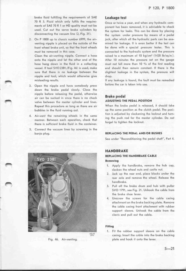
uessel. Il tool SVO 2381 .(Fig. 46) is used, make and should then rem,_in constant. Il there i, the
,ure th8t there is no leakage between the sligftest Ieakage in the system, the pressure will
. nipple 8nd tool. which would otherwise give drop.
_ misleading results_ It any leakage is tound. the tault must be remed'ied
3. ope, ife ,_,ppie a,d fave ,omebody p,e,, befor8 the c,r is taken into use.
' down fhe brake pedal slowly. Close the
nipple betore releasing the pedal, otherwise a k d _
a_,, ,a, be ,u,kgd _,, ,__,,e ifg,e _,, ,o ,fe,k _a e _e a
_ vafve betwee, ife ma,ig, ,yi_,,de, a,d i_,,g,. _DlUS_lH_ 7HE PED_L PO_l7lOH
Repeat this pro,gdure a, long as tfere a,e air When fhe brake pedal is released. it should fake
bubbles in the lluid ,un,_i,g out. up the same position as the clufch pedal, The posi_
h tion is adjusted by slackening the locknut and furn-
4. Alr-Vent t e femalnlng Wheel5 In the 5ame
_ f f k f ing the push rod tor the master cylinder. Do not
ma,ner. etWeen eaC OperatjOn, C eC t at _ i . fi f i k i
if . _i_ _ t b k i_ .d . if t . O,get O flg en t e OC nU _
ere t5 5U IClen ra e Ul In e COn alner.
_. Connect fhe vacuum l'ines by screwing in fhe
banjo plug. REPL_tlH_ _HE PED_L _HDlOR aUSHES
Seg under ''Reconditioning the pedal shalt'', Part 4.
H__DaR__E
REPL_CI__ 7HE H_HDaR_KE C_BLE
Remo_l_g
t 1 . AppIy 1fe fandbrake, ,emove tfe fub cap.
slacken the wheel nuts and castle nuf.
2. lack up tfe rear end. place blocks under the
rear aKle and remove ffe wfeel. Release the
_ handbrake.
_ 3. Pull oll the brake drum and hub with puller
5VO 1 791 . see Fig. l1 . Unhook the cable trom
the brake shoe lever.
' 4. Unscrew the screws lor the cable casing
attachment on ihe brake backing plate. Remove
the cabIe casing lronf atf8chmenf with rubber
' support sleeve. Unhook the cable from fhe
clevis and pull out the cable.
FiHl_g
1 . Fit the rubber ,upport sleeve on the cable
v__O i f bi f b k b k
_os Ca,ing. nsert t e ca e info t e ra e ac ing
Fig. 46. Air-venting. plate and hook if onto the Iever. 5-2_
|

