 |

|
 |


Begin OCR Text:
_ _
P 1 2O. P 1 8OO
- -
_ 2 3 1_ 1o 12
- 'i_'___
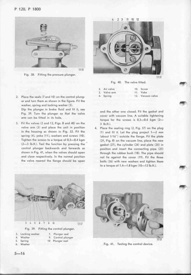
F_ig. 38. FitIing fhe pressure plunger. vg,,o
i_ i__
Fig. 4O. The valve litted. _
_. Air valvg 1O. 5crew '
3. VaJve arm 11. Yoke
2 p_ _h _ (J d _o) th t _ _ 4. 5pring 1__ Vacuum valve
. ace e sea 5 an on e COn rO p Ung-
er and turn them as shown in fhe ligure. Fif the _
washer, spring and lock'ing washer <3)_ _
Dip fhe plunger in brake lluid and lit it, see d th th _ d F_t th k t d
an e o er one c ose . i e gas e an
Fig 39. Turn the pIunger so that fhe valve h _. A .t b_ t. ht _
' _ cover wif vacuum ine. sui a e ig enlng
arm can be fitted in its ho e_ t _ th . o 34 4 k (2
orQue or e screws is . . gm -
3. Fit the valves Cl and 12. Figs. 8 and 4O) on the 3 _b._t.).
valve arm C3) and _place the uniI in po5ition 4. place the sealing ring (l. Fig. 37) on the plug
in the housing as shown in Fig_ 3l_ Fif fhe (1) and lit it. Let the plug project l-Z mm
spring (4), yoke (1 1). washers and screws (1O)_ (about 1(t6'') outside fhe llange. Fit the plafe
Tighten tfe screws to a torque oE O_3_O_4 kgm . (21, Fig. g) on the vacuum line. place the new
(l-3 lb.lt.). Test the tuncfion by pressing ffe gasket (2J . fhe cylinder (24) and plate (2f) in
control plunger backwards and lorwards as position and insert the connecting p_ipe (23)
shown in Fig. 41, when the valves should open through fhe rubber bush (18). The pipe should
and close respectively, ln the normal position not lie against the cover (19). Fit the three
the vaIve nearest the flange shouId be open bolfs (26) w'ith new washers and tighten tfem
to a torque ol 1.4-t.8 kgm C1_12 Ib.ft_)_ _,
3 _ _ 6 _ _ __ v,,_,,_,_
_
''
Fig. 39. Fitting the control plunger.
3. Locking washer 7. Plunger seal
4. Washer 9. Control plunger _ ____
5. Spring 1O Plunger seal
6. w,,he, Fig. 41. Testing tfe control deuice_
5-1 6
|

