 |

|
 |


Begin OCR Text:
P 1 2D. P 1 8OO
_
1O
9 7_
Z 1
_, I l,f __;
__
_
___ _
'i_Oh_l'iiOi 6 f 4 3 V,O,LV_O
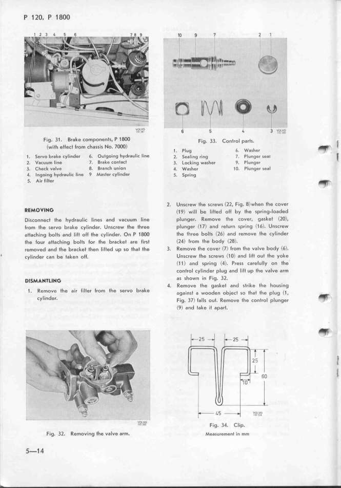
Fig. 31. Brake components, P 18OO F_ig. 33. _on_ro_ parts. _
(with ellect lrom chassis No. l_) _
__ PlU9 6_ Washer _
1. Servo brake Cylinder 6. Outgo_ing hydfauliC line _. _eg_jng ring _. p_u_ger sgai _
2. Vacuum lin8 7. Brake contaCt 3. _ock_ng washer _. p_unger _
3_ Check valve 8_ Br8nch union 4. wgsher _o. p_unger sea_
4. Ingo'ing hydraulic line 9 Master cylinder _. _pr_ing
5. Air lilter _
2. Unscrew the screws (22. Fig. 8)when the cover
REMO_lHG (_q) w_i__ be __i_ted ott by tfe sprjng__oaded
Disconnect tfe hydraulic lines and vacuum line plunger. Remove the couer. gasket (lO).
lrom the servo brake cylinder. Unscrew the tfree plunger (17) and return spring (16). Unscrew
atfaching bolts and lilt olf fhe cylinder. On P 18OO the three bolts (l6) and remove the cyIinder
the lour atlach_ng bolts lor the bracket are tirst (l4) Irom the body (Z8).
removed and the bracket then lilted up so fhat the 3. Remove the cover (7) trom fhe valve body (6).
' cylinder can be taken olt. Unscrew the screws (1O) and liIt out the yoke
C1 1 ) and spring (4). Press carefully on the
control cylinder plug and liJt up the valve arm
D____H___H_ as shown in Fig. 32.
4. Remove the gasket and strike the housing
t. Remove the air filler trom the servo brake aga.inst a wooden ob_.ect so tfa_ tfe p_ug (_
cylinder. F.,g. 37) ta__s out. Remove tfe contro_ p_unger' _
(9) and take it apart.
_
_g
'''''''M_ Fig. 34. Clip.
F_g_ 32_ Removing fhe valve arm, Me6sure_ent jn mm
_-1 4
|

