 |

|
 |


Begin OCR Text:
_
P 1 2O. P 1 8OO
H__DBR__E
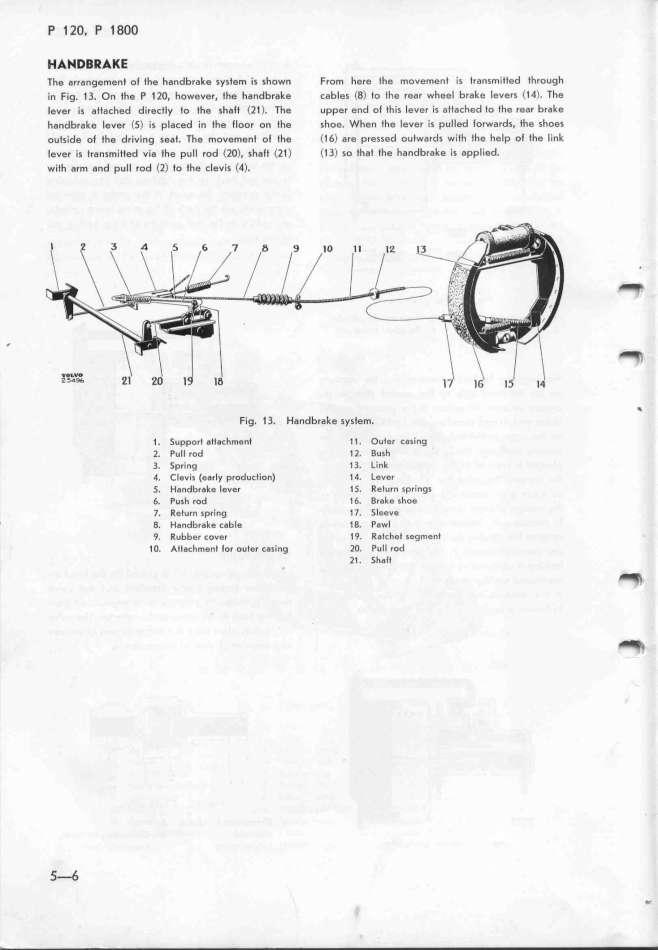
Tfe arrangemenf of the handbrake system is shown From here l_he movement is Iransmitted tfrough
in Fig. 1 3. On the P 1 lO, however. the handbrake cables (8) to the rear wheel brake levers C1 4). The
(ever is attached directly to the shatf <21 >. The upper end of this lever is attached to the rear brake
handbrake lever (5> is placed in the floor on the shoe. W_hen the lever is pulled torwards, the shoes
outside of tfe driving seaf. The movement of tfe (1 6> are pressed outwards with the help ol the link
Iever is transmitted via the pull rod (2O), sfaft <21 ) (1 3) so thaf the handbrake is applied.
with arm and pull rod <2) fo the clevis (4). _
_ _
Fig. 1 3. Handbrake system. _
1 . Support affachment 1 1 . Ouler casing
2. Pull rod 1 l. Bush
3. 5pring 1 3. Link
4. CIevis (earIy production) 14. Lever
5. Handbrake lever 1 5. Return springs
6. Push rod 1 6. Brake shoe
7. Return spring 1 7. 5leeve
' 8. Handbrake cable 18. Pawl
9. Rubber cover 19. Ratchet segMenf
1 O. Attachment for ouler casing lO. Pull rod
21. 5halt _
_
_-6
|

