 |

|
 |


Begin OCR Text:
P 1 2O. P 1 8OO
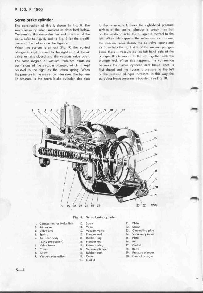
_ervo brake Eyli_der
The construction ol tfis is shown in Fig. 8. The Io the same e_fent. Since the right-hand pressure
servo brake cylinder lunctions as described below. surface ol the control plunger _s larger than that
Concern_ng the denomination and posifion of the on the leff-hand side, tfe plunger is moved to the
parts. reler fo Fig. 8. and to Fig. 9 lor the signili- lelf. When th_is happens the valve arm also moves.
cance ol the colours on the ligures. the vacuum valve closes. the air valve opens and
When the system is Bt rest (Fig. 9) the control a_r flows ínto the right side of tfe vacuum plunger.
pIunger is kept pressed fo fhe right so thaf fhe air S_nce ffere is vacuum on the lelt-hand side ol the
valve remains closed and fhe vacuum valve open. plunger. fhis is moved to the lelt together with fhe
The same degree of vacuum therelore e_ists on plunger rod. When this happens. the connecfion
bofh sides of the vacuum plunger. which is kepf between the master cylinder and brake lines is
pressed to the right by the refurn spring. Wfen lirst closed and the hydraulic pressure to the lelt
the pressure in the master cylinder rises, the hydrau- ol the pressure plunger increases. In this way the
lic pressure in the servo brake cylinder also r_ises outgoing brake pressure _s boosted, see Fig. _ O. _
_
_ _
__
Fig. 8. Servo brake cylinder.
1 . Connection lor brake l_ne 1 O. Screw l1 . Plate
2. A_r valve 1 1 . Yoke 2l 5crew
3. Valve Drm 1 l VacuuM valve 23 Connecting pipe
_. Spring 1 3. Plunger seal l4. Vacuum cylinder
5. A_r tilter body 14. Rubber ring 25 Plate
(early production) 1 5. Plunger rod l6 Bolt
6. Valve body 1 6. Return spr_ng l7. G8sket
7. Cover 17. Vacuum plunger 28. Body
8. 5crew 1 8. Rubber bush 29. Pressure plunger
9. Vacuum connection 1 9. Covei 3O. Control plunger
2O. Gasket
5_
|

