 |

|
 |


Begin OCR Text:
_
_
__ç
/
P 1 2O. P 1 8OO
Rea__heeI b_ake U_ilI rest against an adjusting device (Fig. 6). This means
Th h _ b _ ._ . h. . that the servo eflect is only obtained on the pri-
e Feaf W ee ra e Unl 5 In t l5 5y5fem COn5l5t h
_ d b k _ _h _. _ _ F. 2S mary s oe. so that this type operates more directly
O rUm fa e5 O e Imp e_ ype, 5ee Ig. .
E h h _ b k _ h d b_ _ _ than the other fypes on ffe P 12O. The brake shoes
aC W ee ra e Unl aS a OU e-aC Ing Cy In- __
d (F. S) d _h _ d _ h b k h are se -centring since they can be displaced rad_i_
ef, Ig, an e OWef en 5 O t e ra e 5 oe5 ally at the support poinfs.
_ 2 _ 4 . / '/
_\ii.tii_,j
,j_
,\ __ '1 ' _ /
_ lI 2 3 _ VI_OVLdViUi
Fig. 6. Adjusting d8vice.
1. Brake shoe 3. Body
l. Plunger 4. Adjusting screw
_ Fig, 5. Wheel unit cylinder, rear wheel.
1 . Rubber cover 3. p_unger _ea_ MaIte_ _yli_de_
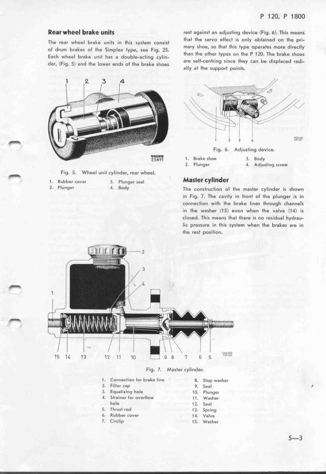
2. Plunger 4. BDdy The cons_,uc___on o_ _he mas_e, cy___nde, __s shown
in Fig. 7. The cavity in lront ol the plunger is in
connection with the brake lines through channels
in the washer (1 S) even when fhe vaIve (14) is
closed. This means that there is no residual hydrau-
lic pressure in this system when the brakes are in
the rest position.
t Fig. 7. Master cylinder.
1. ConneCtion for brake line g. 5_op wa__e_
l_ Filfer cap 9. 5eaI l
3_ Equalizing hole 1 O. Plunger
4. 5trainer for overtIow _ (. Wa_he,
hole _2. 5eaI
5_ 7hrust rod (3. 5p,_ng
6 Rubber cover (4. Va_ve
7_ CircIip 15. Washer 5-3
|

