 |

|
 |


Begin OCR Text:
o
_
P t 2O. P t 8Oo
Fro_l _feel brake u_iI_ , , , , , ,
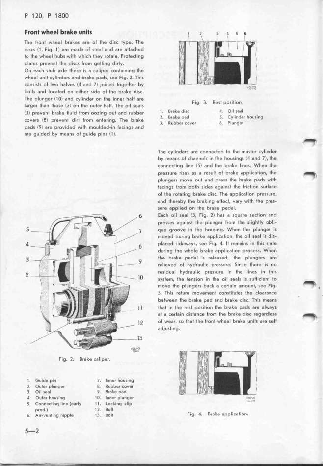
The Iront wheel brakeS are of fhe d,,, fype. The
discs (1 , Fig. 1 ) are made of ,fee_ a,d a,e affa,hed
to the wheel hubs with whi,h fhey ,ofafe. p,ofe,f_,,g
Plates prevent fhe discs from geffing di,fy.
On each stub a_le there i, a ,a_iper ,o,fa_,,_i,g fhe
wheel unit cylinders and b,ake pad,, See F_,g. 2. Th,_S
Consists of two halveS (4 and J) _o_,ed foggfhe, by
bolts and located on either S,de of fhe b,ake d_,,,. ;_c___j
The plunger (1 O) and cylinde, o, fhe _,,,e, h,lf ,,e
Iarger fhan lfose (l) on fhe oufe, ha_f. The o_,_ ,,,l, F_9_ 3_ ReSf position_
(3) prevent brake lluid lrom oozi,g ouf a,d ,ubbe, 1 . Brake diSc 4. o,__ ,ea_
CGver, (0) prevenf dirf f,om e,fe,,,g. The b,ake l_ Brake pad 5. Cy_inde, hou,_ng
padS (q) a,e p,ov_ided w_ifh mou_ded_.i, fa,,i,gS a,d 3_ RUbber ,OVe, 6. __u,ge,
are guided by means of guide p,,, (_ >. The cylinders are connected to the ma,fer ,yl,,de,
by mean5 O1 Cha,,e_5 j, fhe houSj,gS (4 a,d J), fhe
CO,neCting line (5) a,d fhe b,ake lineS. Whe, fhe
ßre55Ure fi SeS aS a reS Ult of brake appli,afío,, fhe _
pIUng Bf5 mOVg O Uf a,d p,eSS fhe brake pad, wiff
lac_ings from both sides agajnsf fhe f,j,fio, ,u,fg,e
Of the fOfa J_,g bfake djs,. The app_i,afio, p,essu,e,
and thereby the brak ing effe,f, va,y w,fh fhe p,e,-
5Ure appl_ed on the brake peda_.
6 EaCh oil Seal (3, Fig. 2) ha, a ,qua,e ,e,fion a,d
_ presses against the plunger f,om fhe ,lighf_y obli.
_ qUe g,OOVg in fhe houSi,g. When fhe plu,ge, i,
moVed during brake aFplicgfjo,, fhe oil ,eal iS diS-
4 g pl,,ed ,_,dew,yS. Se, F.,g. 4. lf ,em,.,,s .,, fh.,, ,fafe
during the whote brake appli,atio, pro,e,s. whgn
3 g the _rake pedal is reIea,ed, fhe plu,ge,S a,e
fel'i0Ved Ol hydra Uli, pressu,e. _i,,e fhere i, ,o
2 _o re5idual hydrautic preS,u,e i, fhe li,e, i, fhi,
Sy5tem, the tenSion in fhe oil ,eal, i, Sulfi,ig,f fo
mOVe the plungers back a cerfai, amou,f, ,ee Fjg. _ _
_t_ Tfj5 retUr, mOveme,f ,o, SfifufeS ffe ,lea,a,,e
betWeen the b,ake pad a,d brake di,,. Th,S mea,, ' '
Il thaf in the rest positìon the brake pad S a,e alwgy,
at a Certain di5fa,,e ffOm ffe b,ake diS, ,egardlg,, _
_ 2 o1 wear, so thaf fhe lront wheel b,ake unif, g,e ,e_f
adjusting.
f 1_'
Fig_ l_ Brake caliper. '''''
1 _ Ciuide pin _. _nne, hou,ing
2, Ouler plunger g. _ubbe, ,ov,,
3. Oil Seal g. _,ak, p6d
4_ Outer houSi,g _ o. _nne, p_unge,
5_ ConnecIing line (early _ _ . _ock_ng ,__,p 'i_'_'j'_'_
prod_) _ l. _ol_
6_ Air_venting nipple _ 3. _olf Fig. 4. _,__ke appl_,,af_io,.
_-2
|

