 |

|
 |


Begin OCR Text:
_
' P 1 2O. P 1 8OO
D E _ _ R l P T I O N
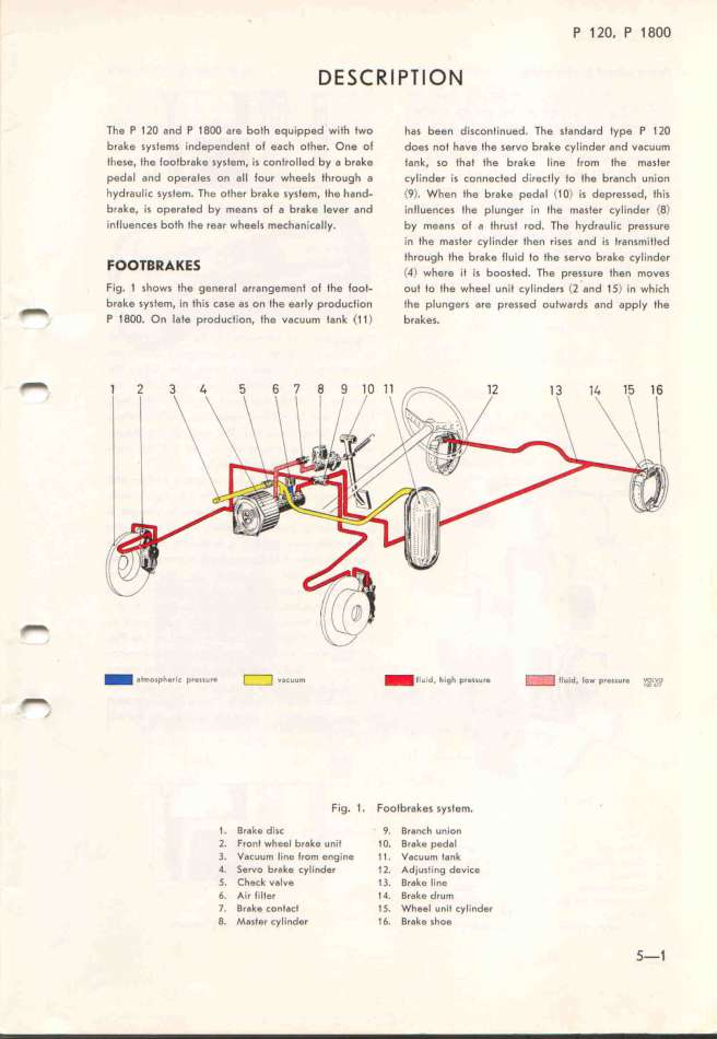
The P 12O and P 18OO are botf equ_pped wifh Iwo has been dėscontinued. The standard type P 1 2O
brake sysfems independent ol each other. One ot does n Dt have the servo brake cyIinder and vacuum
tI)ese, the footbrake system, is controlled by a brake tank, so tfat the brake line from fhe masfer
pedal and operates on 8Il lour wheels through a cylinder is connected directly to the branch union
hydraulic system. The oIher brake system. the hand- <9>. When the brake pedal (1 O) is depressed. this
brake, is operated by means ot a brake lever and intluences the plunger in the m8sfer cylinder (8)
influences both the rear wheels mechanic8lly. by means ol a thrust rod. The fydraulic pressure
in the master cylinder then r'ises and is f_ransmitIed
Foo_____E_ through the brake lluid to the servo brake cylinder
(_.) wfere it is boosted. The pressure fhen moves
Fig_ 1 shows the general 8rrangem8nt ot the foot- ouf to the wheel unit cylinders (2 and 15) in which
brake sysfem, in this case as on the early production the plungers are pressed outwards and apply the
_ p g i d <
1 OO. On ate prO UCtlon, the _aCUUm fank 1 1) brakeS.
_
__lmosphe_ic p.essu._ _ v6cuum _ E_uid. hi9_ p.essu,e _ (1uid, Eow p,essu.e ?._oL__
__ Fig. 1. Footbrakes system. _
1. Brake disc 9. Branch union
2. Fronl wheel brake unit 1O. Brake pedDl
3. Vacuum line Jrom engine 1 1. VDcuum tank
4. Servo brDke cylinder 12. Adjusling device
5. Check vDlve 13. Brake line
6. Air tiIIer t4. Brake druM
7. Brake contact 15. Wheel uniI cyIinder
8. Master cylinder 16. Br8ke shoe 5-1
|

