 |

|
 |


Begin OCR Text:
P 1 2O, P 1 8OO, PV _44
IH_7_LLl_G _oe
1 _ Lilt up the rear a_le and lit the torque rod. Slide
the support arms into the retainers on the body
and tif fhe rubber blocks, washers and nuts.
lighfen the nufs only a couple oI turns to begin
with.
2. Fit the springs, retainers and rubber blocks in
po5ition_ Litt Up the rear a_le wifh a jack. _eve__e _i _ivi_g __ide
Tighten the support arm nuts. Fit the shock
absorbers, shock absorber straps and track rod.
3_ Connect up the universal joint at the llange.
Connect up fhe brake fIuid hoses. Connect up
the handbrake cables. Air-venI the brakes and
adjust the handbrake. Fill up wifh oil.
Use only hypoid oil. _,
4. Fif tfe wfee_s gnd wfee_ nufs. _ower ffe car Hee_ _,,O_Lq__O
and tighten the wheet nuts. Fig. 34. Correct tooIh contaCt. _
_DlU57lHG 7HE 7OO7H CO_7_C7 engine oiI. Tfe marking paint must not be foo fhin
When the rear a_le is assembled. if is e_treme_y 5ince this can give a laulty result_
important fo ensure fhat tfe crown wfee_ and drive All the teeth should be smeared wiff a fhin coating
pinion are correctIy litted relafive to eacf ofher. Tfis ol marking paint_ The pinion 'is tfen rotated ten fo
does not only concern the clearance befween ffe twelve times in boIh directions. at the same time the
teeth but also the tooth contact. Wfen fhe footf crown wheel is braked hard by using a wooden
confact 'is correct, fhe stresses fo wficf tfe teetf are wedge or similar device_ The marking paint on fhe
subjected when the car is drjven are distrjbuted over crown wheel teeth is tfus removed while the pinion
the greafer part ol the 1ooth surlaces. ln fhjs way teeth contact them, so that a clear picture ol the
tooth breakage is avoided. as we_l as abnormally e_tent and position ol the tooth contact is obtained.
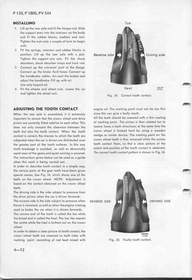
rapid wear ol the gears.and qujef running is ensured. _he correct tooth contact pattern is shown in Fig. 34.
Tfe instrucfions given below can be used as a guide
when fhis work is being carried out.
In order to describe tooth contact in a simple wgy.
the various parts ol the gear teeth have been given
_
special names. See Fig. 34, wfich shows one ol ffe _
teeth on the crown wheel. NOTE. Adjusfmenf is
based on the contact obtained on the crown wfeel
feeth.
The driving side is the side subject to pressure lrom __
the drive pinion when the car is driven lorwards.
_he reverse side is the side subject fo pressure when _eve__E _lDE D_lvf__ SlDe
thecar is reversed. as well as when theengine is bejng
used to brake the car when it is dr'iven lorwards.
The narrow end ol the tooth is called ffe foe wfile
the broad end is called the heel. The toe lies nearesf
the centre while fhe heel is lurthest out on the crown
wheel.
In order to obtain a clear picture ol footh contact. the
crown wfeel teetf are smeared on botf s__des w_iff W_,L_W6_
marking paint consisting of red lead mi_ed wifh Fig. 3_. Faulfy tooff confacf.
4-1 2
|

