 |

|
 |


Begin OCR Text:
_ _ _ _ _
P 1 2O, P t 8OO, PV _44
dismantling and then fit the tront pinion bearing pinion gauge sfould be higher than Ihe adjusfer
(2J). Fif the wrench SVO l4O4 and the press fi_ture. and if it ís marked '' -_ '' the pinion
fool SVO 1845 on fhe front end of the pinion gauge should be lower than the adjuster ti_-
and puII in the pinion. see Fig. l3. ture when adjustment is correct.
5. Replace the press tool SVO 1 845 wifh a washer
and nut. Tighten the nut fo a forque of l8-3O
kgm. (lOO-22O Ib. ft.). Then check the pinion
begring tension. It should be reIatively easy to
rofate the pinion (1 1 .5-23 kgcm = 1 O-lO
Ib. in.). There should be no looseness. Bearing
fension is adjusted by means of shims (26) on
the front pinion bearing.
6. There should be a cerfain nominal measurement
(A, Fig. 24) to the centre line of tfe crown
_ wheeI. Due to tolerances _in manufacture. how-
ever, there are deviations trom this nominal
measurement. The deviation is shown on the voivo
d _ _ h . . b _ 2t53t
groun sur ace o t e pinion y means o a F_,g. 26. Se___,ng _he _,nd_,ca_or _o zero.
tigure with a pIus or minus sign. If there is a
_ plus sign 'in fronf ol the figure. the nominal
measurement ěs fo be increased and, in the
case of a Minus sign. the nominal measur8ment
is to be decreased. The deviation tigure shown
on the drive pinion is in thousandths ol an inch.
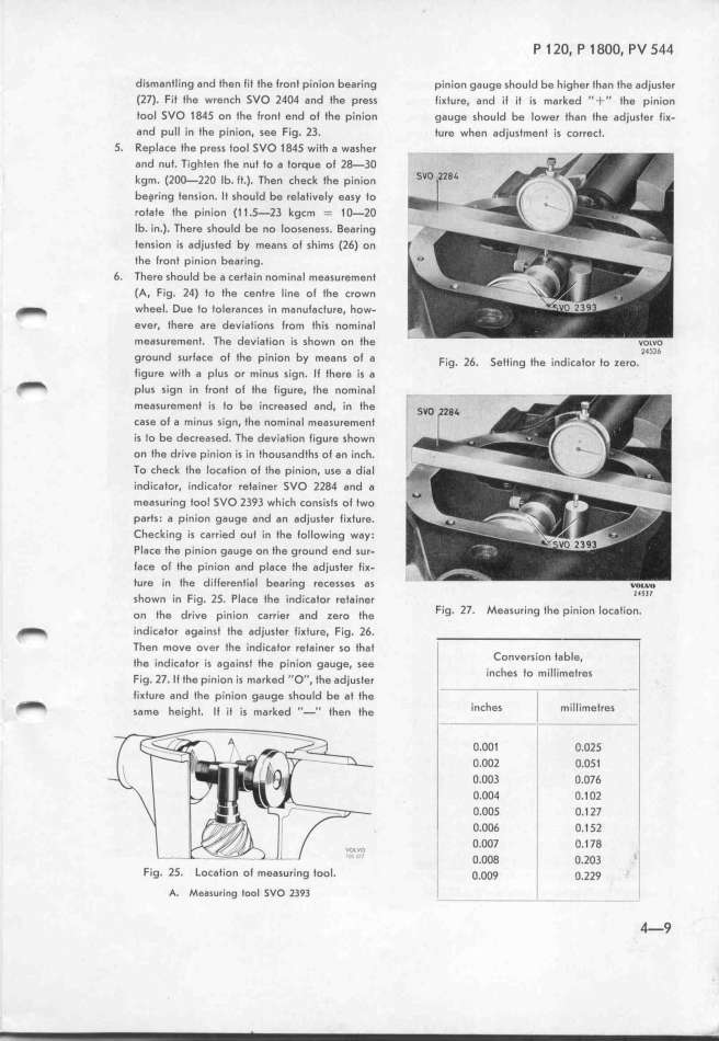
To check the location ol the pinion, use a dial
indicator. indicator retainer SVO 2l84 and a
measuring tooI SVO l393 which consists of two
parfs. a pinion gauge and an adjuster ti_ture.
Checking is carried out in the tollowing way.
Place the pinion gauge on fhe ground end sur-
face of the pinion and place the adjuster tiK-
ture in the differential bearing recesses as ____
h h d Zl5Il
s own in Fig. 25. P_ace f e in icator retainer
on _he dr.,ve p.,n._on carr.,er and zero _he Fig. l7. Measuring the pinion location.
_ índicator against the adjuster fi_ture, Fig. 26.
Then move over tfe indicator retainer so that _ _
_
Conversion table,
the indicator is againsf the pinion gaUge, see
k d ,, , h inches fo millimetres
Fig. 27. l I the pínion is mar e O' , t e adjuster
fiKture and tfe pinion gauge should be at the _ i - - -
_ same he_,gh_. __ ___ _,s marked ,,_., _hen _he
inches _ miIlimetres
O,OOf 'li O.O25
O.OO2 _ O.O51
O.OO3 _ O.O76
O.OO4 O.1 Ol
O.OOS
O.1 27
, O.OO6 O.1 5l .
i o.oo7 o.1 J8 l
_
O.OO8 O.lO3
Fig. 25. Location of measuring tool. o.ooq _ o.zzq
A. Measuring tool sVo _393 - - ' - l
4-9
|

