 |

|
 |


Begin OCR Text:
___
__
_ __o___v_u
_ _ P 1 2O, P 1 8OO
_ D E__ _ _ __ _ O _
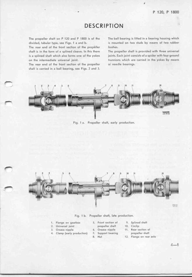
' The propeller shalt on P llO and P 18OO is ol the The ball bearing is fitted in a bearing housing which
' divided. tubular type. see Figs. 1 a and b. is mounted on two studs by means ol two rubber
The rear end ol the front secfíon ol the propeller bushes.
_ sfalt is in the lorm ol a splined sleeve. In this there The propeller shatt is provided with three universal
is a splined shalt which also forms one of the yokes joints. Each joint consists ol a spider wiff four ground
on the intermediate universal joint. trunnions which are carried in the yokes by means
The rear end ol fhe front section ol the propeller o; needle bearings.
shalf is carried in a ball bearing. see Figs. 2 and 3.
_
-
fl
_ __
Fig. 1 a. PropeIIer shaft, early producIion.
_
6 7 g _ _o __
__
li
Fig. 1 b. Propelter shaft. Iate production.
l 1. Flange on gearbo_ 5. Front section oJ 9. Splined shaJt
2. Universal joinl propeller shalt 1O. Circlíp
3. Grease nipple 6. Grease nipple 1l. Rear section ol
4. ClaMp (early producIion) 7. 5upport be8ring propeIIer shaJt
8. Nut 1l. Flange on reDr a_le 4-t
|

