 |

|
 |


Begin OCR Text:
P 12O, P t8OO
4. The pump is removed ag fo__owg. and the valve rod with a magnet or a pointed
Ungšrew the bo_e whišh hoIdg the pump through piece of wood which is pushed intO the ValVe
the hole in the eKtension piece (58). Attach rod drilling_
puIIer SVO 2418 into the place of the v8lve 3. Clean ehe various parts thoroughly. The drilling
seating and pull out the pump, see Fig_ 12, of the valve rod late production is cleaned with
5. DigmantIe and check the varjous partg of the a 3.1-3.2 mm drill and the valve hole With a
pump. 1.1 mm dfill. Fof early produCtion ValV0 rodS_
6 Th d _ f__ d _ th uge a 3 1-3 2 mm drill and O.7 mm dfill fe_
. e pump an pUmp va Ve ar0 l e In e _ '
reverge order to removing. Cheš_ that the SpeCt_Vely_
washer for the oil pump plug (4, Fig. 4) is in 4. Fit the parts in the rev0rSe Order tO remOV_n9_
good condition. FiII up with oil. REMOVING 7HE OVERDRlVE
Che_ki_g the relie_ volve 1_ CarrY out oPerations 1-4 Under ''RemOVin9 th'
' _. D_geng_ge the overdrive so ehae any regidua_ gearboK'' in Part 4 (43) of the ServiCe ManU8I
_ oi_ preggure ig removed (_ate produštjon). on for the M 3O_M 4O gearboK_ AISo dra_n OUt the
, ear_y production, engage and digengage the oil from the overdrive.
overdrive 1O-12 times in order to do this. JQck 2. Disconnect the cable to the solenoid_
up the vehicle and place blocks under the front 3. ungšrew ehe boltg w__išh hold the overdrive unit
and rear aKles. Remove the drain plug and let eo the _intermediate fIange and remove the
_ the oil rUn oUt into a Container_ overdrive unit.
2. Remove the plug and take ouf the spring (11)
and vaIve pIunger (12). pu_1 out tfe va1ve seae- DlSMANTLING 7HE OVERDRIVE
ing(1O)with the help of a small hook,see Fig, 13, The following section describes how the overdrive
3. Clean and šheck aIl partg ehorough_y. Fit the unit is fully diSmantled. It iS, howeVer, SeldOm
partg jn ehe reverse ordgr to removing. necessary to dismantle it completely_ When CafrY-
ing out dismantling, therefore, follow the appro-
Cleo_.i_g the _o_trol volve priate parts of the instructions given below_
_. Djgengage the overdrive so that any regjdual 1. Remove the covers over the oil Stfainer and
oil preggure js removed (late production). On over the lever C13) for the control VaIVe_ Re-
ear_y produšeion, engage and dÝgengage the move the oil strainer_ Unscrew the boltS and
oyerdrive 1o-12 timeg in order to do (hig. lift out the solenoid (18)_
2. Remove the p_ug over ehe šonero_ va_ve ag weII 2. Bend down the locking pl8tes, UnSCreW and
as the spring(49), tappet(52), ball(53)and valve remove the nuts for the PiSton PreSSUre Plate'
rod (16). The baII can be lifted up with a small C56)_ _Remove the Pressure Plates_ Pull out the
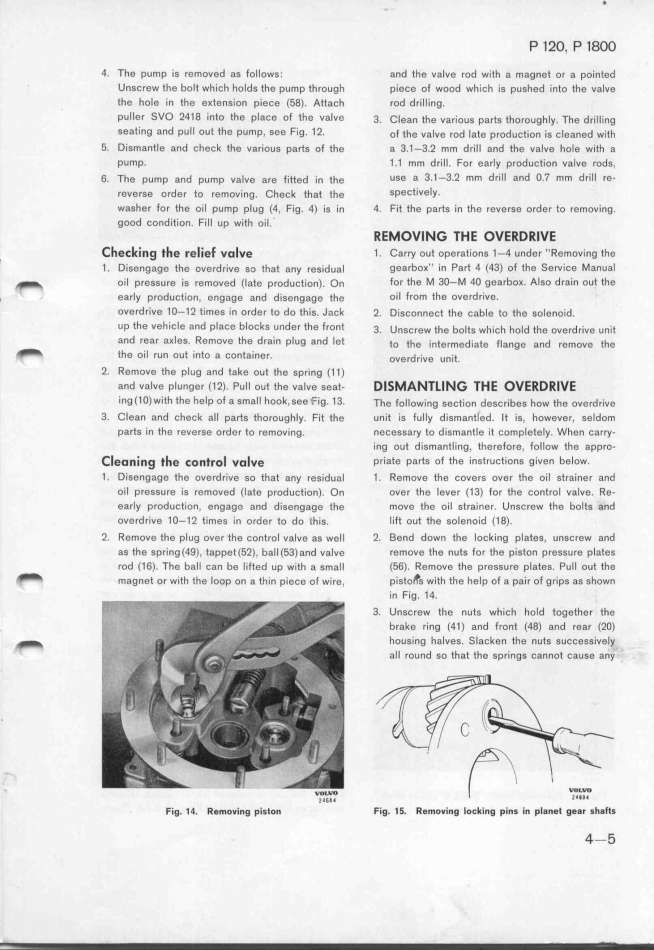
_ magnee or wjth ehe Ioop on a thin piece of wire, pisto s with the help of a Pair of griPs as shown
in Fig. 14.
3. Ungcrew the nuts whieh hold together the
brake ring (41) and front (48) and rear (2O)
_ housing h8lves. Slacken the nuts successiv8ly
all round so that the springs c8nnot cause a_y
__lWO6Jl
F_ig. __. ffg_ov_ing pis_on Fig. __. ffg_oving Io_king pins in plangt ggar shafts
4-5
|

