 |

|
 |


Begin OCR Text:
P 1 2O, P 18OO
D E _ _ R l _ _ _ O _
CUnless otherwise stated, the figures in brackets refer to Illustration B)
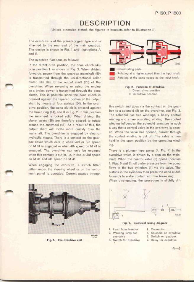
The overdrive is of the planetary gear type 8nd is
attached to the rear end of the main gearboK.
The design is shown in Fig. 1 and Illustrations A
and B.
The overdrive functions as follows.
In the direct drive position, the cone clutch (43) _ ,
is in position l as shown ìn Fig. 2. When driving _ Non-rotating p8rts
forwards, power from the gearboK m8inshaft (59) _ Rotat_ng at a higher speed than the input shaft
is transmifted through the uni-directional roIIer _ Rotating at the samG sPeed as the inPut sh8ft
_ clutch (33, 34) to the output shaft (25) of the
ove,d,,ve. when ,eve,g;,g ,, ,,_,,g ih, ,,g_,,, F_,g. _. F,,,_.,o, o_ o,,,d,.,,e
' as a brake, power is transmitted through fhe cone l Direct driue position
çJuiçh. Thi, i, po,,ib_e ,i,çe ehe ço,e ç_u_çh i, Il Ouerdrive position
pressed ag8inst fhe tapered portion of the output
_ shaft by means of four spríngs (54). In the over-
d,jve po,_,e_,o,, ehe çone ç_ueçh _,, p,e,,ed aga_,n,i thiS SWitCh and goes vìa the contact on the gear_
ehe b,ake ,_,,g (4_), ,ee _i _,, F_,g. 2. in eh__, pog_,e_,o, boK to a solenoid (5) on the overdrive, see Fig. 3.
ehe gunwheei __, ioçked ,oi_,d. when d,_,,_,,g, ehe The Solenoid haS two windingS, a heavy Control
p_a,ee gea,, (3g) a,e ehe,e_o,e ça,,ed eo ,oeaee winding and a fine operating winding. The control
a,o,,d ehe ,,,wheei (q6). A, a ,e,u_e of eh_,,, ihe winding influences the Solenoid armatUre in such
ouepue ,ha_ w___i ,oiaee mo,e q,_,çk_y eha, ihe a way that a control valve in the overdrive is open_
ma,_n,hafe. The o,e,d,_,,e _,, e,gaged by e_eçi,o- ed_ When the valve has opened, current through
hyd,au_,_ç mean,. The,e _,, , ço,eaçe o, ehe gea,- the control winding is cut off. The valve is then
boK çove, wh_,çh ç,e, _,n whe, 2,d o, 3,d ,peed held in the open position by the operating wind-
o, M 3_ _g e,gaged o, when 4eh ,peed on _ q_ _,g l,g.
engaged. The overdrive can only be engaged There is a plunger type pump (4, Fig. 4) in the
when this contact is cut in, i.e. in 2nd or 3rd speed overdrive which is driven by a cam on the main-
on M 31 and 4th speed on M 41 . shaft. When the control vaIve (6) opens (posit'ion
whe, e,gag_,,g ehe ove,d,_,,e, a ,w_,içh f_,eeed 1 , Figs_ 5 and 6), oil under presSure from the pump
e_,ehe, u,de, ehg ,iee,_,ng whee_ o, o, ihe _,,,i,u- flowS to the two CylinderS (1 ) Yi8 the v8lve. The
_ m,,e pa,ei _,, ,p,,,i,d _,,,e,e p,,,,, eh,,,gh pistons in the cyl,nders then press the cone clutch
' forwards to make contacf with the brake ring.
, When disengaQing, the procedure is slightIy dif-
__ _
,1_
l ' Fig. 3. Electric8l _iri,g diBgr8m
1 . Lead from fusgbo_ 4. _onneçtDr
_--- - - -- v . 2. Warning lamp for fi. Solenoid on ouerdrive
jU_'_U_O_ overdrive 6. Switch on gearboK
Fig_ 1. The overdrive u,it 3. Swltch for overdrive 7. Relay for overdrive
4-1
|

