 |

|
 |


Begin OCR Text:
P 12O, P 18OO
5. Fit on the control cylinder (41) and hook on return spring (34). Unscrew the bolts and lift off
the return spring. the controI cylinder.
6_ Fit the gearbo_ in accordanCe with the instruc- D_sMANr__NG
tionS giVen in GfoUp 43. Remove ehe ,ubbe, dug_ çover (3g) a,d eh,uge
7. Bolt the plate onto the lower front p,rt of the ,od (3p) _emo,e the ç,,,ç_,,p (3g) a,d iake out ihe
flywheel houSing. p_u,ge, '(45) a,d gp,__,g (4j).
CLUTCH CONTROLS lNspecr_NG
_oste_ Ey_i_de_ See under ''Inspecting the master cyIinder'',
ffEMov_NG the appropriate parts of which Qpply.
Disconnect the pipe (1 O) from the master cy- AssE___lNG
linder <9)_ Remove the pedal ret8ining bolt. Un- D_,p ehe p_u,ge, (45) a,d gga_ (44) _,, b,ake e_u_,d
SCrew the botts and lif,t off the cylinder. a,d e_,i ihe ,ea_ o, ihe p_u,ge,. F_,i ihe gp,_,ng
_ DlsMANrLlNG (O2) and ptunger in the cylinder (O1). Fìt the circlip
_ . _em,,, eh, ,,p ,,d ,mpey ,,,i ih, b,,ke i_,.,d. (39). thrust rod (37) and rubber dust cover (38). _
2. __ake off the rubber cover (16) and remove the lNsrALLlNG
circlip (15)_ Take out the plunger (t2) and the _,gia___,ng _,g do,e _,, ehe ,,,e,ge o,de, io ,e-
other partS from the cylinder. mov_,,g. A_,,-ve,i ihe gygiem a,d ad__ugi ihe ç_,eçh
3_ Remove the retainer (3) for the check-valve ,e_eage io,k i,a,e_. _
(8) from the plunger and separate the parts.
lN, _E_rlNG Air-ve_ti_g the hydrouliE system
' Check that the container is filled with brake
._sh aII the parts in clean spirit and then check i_u_,d. _emo,e ihe ,ubbe, ,ap o, ehe a_,,-ve,t_,,g
tt __ for wear or other damage. ,_,pp_e (43) o, ihe ,o,t,o_ ,y__,,de, (4_ ) p_açe a
The cylinder muSt be Carefully eKamined inter- hoge o, ihg ,_,pp_e a,d _,mme,ge ihe oihe, e,d
_ naIly_ There must be no scoring or scratches on oi ihe hoge _,, a ço,ia_,,e, e_,__ed w_,ih b,ake i_u__d
the polished surface. Small scratches can be '
_ d _th i_ _ eh I 2 3 4 5 G 7 8 9 lO ll l2
C eane Up Wl Uey l,e emery C O .
EKamine the plunger seals for cracks or scoring
on the edges. Also check that they ,re not swollen
up due to incorrect brake fluid or similar. The
seals must be replaced if there are the least signs
of any defects.
ASSEMBLING _
g
. t _ Fit the S0a_S (1 1 ) On the plunger (12). ASSemble
the check-valve (8), retainers (3, 7), spr_ing (5)
and plunger (1 2).
2_ Dip the plunger and check-valve in brake fluid
and fit them in the cylinder. Fit the thrust _od _
(1 7), washer (14) and circIip (15). Place on the
rubber dust cover (16).
INSrALLING ,
Installing is done in the reuerse order io re- _
moving, Fill up with brake fluid and air-vent ehe v,g,L?,?
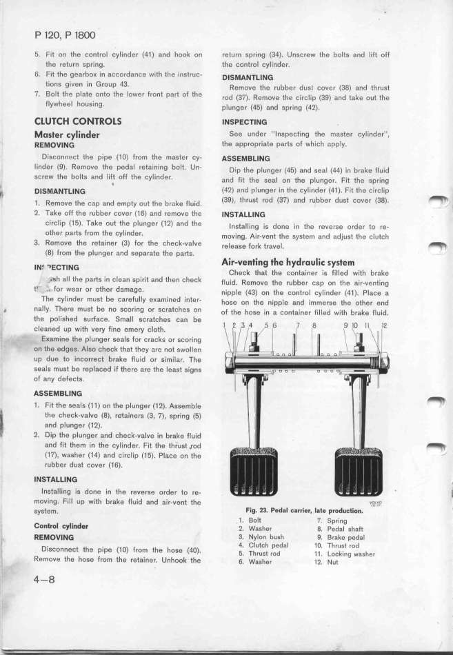
gystem. Fig_ 23_ Pedal c8rrier, Iate productio_.
c l l. d 1. Bolt 7. Spring
OlltrO _y Ill $r _. waghe, g. peda_ gha__
ffEMOV_NG 3. Nylon bush 9. Brake pedal
D, e eh . (_o) F 4. Clutch pedal 1O. Thrust rod
ISCOnneC e plpe rom the hose (4O) _ Th d _ _ k
_ ih h i h ' _ rUSt rO 1 . OC Ing WaSher
emOVe e OSe rom t e reta'iner. Unhook ihe 6. wggher __. _ue
_ 4-8
|

