 |

|
 |


Begin OCR Text:
P 12O, P 18OO
_ __ _ZOI7_
1OIBO
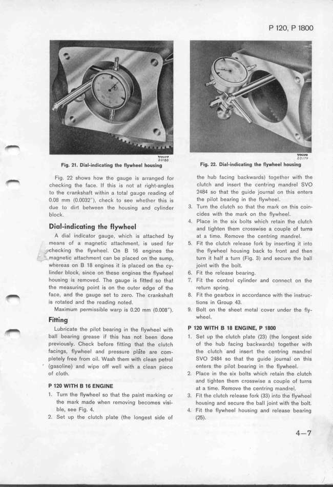
F__g. __. D__g_.__nd_;Eg___ng __g f_ywhgg_ houg__ng Fig. _2. Di8l_indiCating thg Ilywhggl houSing
F_,g. 22 ,how, how the ga,ge _,g a,,a,ged Fo, the hub facing backwards) to_ether with the
_ ,h,,k_,,g th, Fa,,. _F jh_,, ,_, ,oj aj ,_,ghj-,,g_,, cIutįh a,d inse_ jhe centring mandreI SVO
to jhe e,a,kghaFt w_;jh_j, a eoja_ gauge ,ead_,,g oF 2484 so that the guide journal on thiS enters
o.og mm (o.oo32__), ,h,,k to ,,, wh,jhe, jh_,, _,, the pilot bearing in the flywheel_
d,, t, d;_ b,jw,,, jhe h,,,_,,g ,,d įy_;,d,, 3. Turn the clutch so that the mark on thiS Coin-
b_,,k. cides with the mark on the flywheel.
_ d _ __ _ _ 4. Place in the ,iK bolts which retain the clufch
Dio -in i_oting t e _ ee and jighjen them crosswise a couple of turns
A dial indicator gauge. which is attached by at a time. Remove the centring mandrel_
means of a magnetic attachment, is used for 5. Fit the clutch release fork by inserting it into
._checki,g the flywheel. O, _ 16 engines jhe the flywheel housing back to front and then
- magnetic attachment can be placed on the sump, turn it half a turn (Fig. 3) and secure the ball
whereas on B 18 engines it is placed on the cy_ joint with the bolt.
linder bIock, since on these engines jhe flywheel 6. Fit the rele8se bearing.
houging j, rgmoved. The gauge ig fjjjed go jhat 7. Fit the control cylinder and connect on the
the measuring point is on the outer edge of the return Spring_
_ face, and the gauge set to zero. Th8 crankshaft 8. Fit the gearboK in accordance with the instruc-
is rotated and the reading noted. tions in Group 43.
MaKimum permissible warp is o.2o mm (O.oo8''). 9, Bolt on the sheet metal cover under the fly-
F. . wheel
ittIng '
_ _ub,;,aj, jh, p;_ot bea,;,g _,, ehe F_ywh,,l w_,jh P 12O Wl_H B 18 ENGINE_ P 18OO
ball bear_ing greaee if jhis hag noj been do,e 1_ Set up the clutch plate (23) (the longest Side
previously. Cfeck before fitting thaj jhe clutch of the hub facing backwards) together with
fa,i,Q,, f_ywhee_ a,d p,eggu,e plaje a,e įom_ the clutch and inSert the centring mandrel
plgjgly f,ee f,om oi_. Wa,h jhem wjjh ,leg, pgj,ol SVO 2O84 so that the gUide journal on thiS
_ (gasoline) and wipe off w,ll with a įle8n piece enters the Pilot bearing in tfe fIYWheel_
of c_ojh. 2. Place in the siK bolts whiCh retain the clutch
and tėghten them crosswise a coupIe of turns
P 12O Wl_H B 16 ENGINE aj a j_me. _emove jhe ,e,t,i,g ma,d,e_.
1. Turn the FIywheeI so that the paint marking or 3. Fit the clutch release fork (33) into the flywheel
the mark made when removing becomes v'iei- housing and secure the ball joint with the bolt.
ble, see Fig. 4. 4. Fit the flywheel fousing and release bearing
2. Set up the cIutch plate (the longest side of (25). 4-7
|

