 |

|
 |


Begin OCR Text:
P 12O. P 18OO
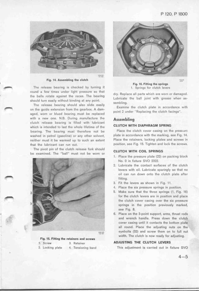
Fig, 14_ AsSembling th$ tIUtth '''''''_'' l _..?,ff_
l Fig. 16. Fittingth$$prings
_ The release bearing is checked by turning it _. jp,,ngs _o, c_,tc_ _g,g,g
round a few times under light pressure so that d R __
, the ba_ig ;otate agg__,gt the ;ašeg The bear_,,g y_ eplaCe a p8_S WhiCh a,e WOrn Ol d8maged.
ghouid tu;, eag.,iy w,.thout b.,,d.,,g at g,y po.,,t Lubricate the ball joint with grease when as-
The ;eieage bea,.,,g shouid aigo gi._dg eńg.,iy sembling.
_ o, the g,_,de eKte,g.,o, _,om thg gearboK A dam EKamine the clutch plate in accordance with
aged, wo,, o, biued bea;.,,g must be ;epiaced point 2 under ''Replacing the clutch facings''.
with a new one. N.B. During manufacture the A__e_b____g
clutch release bearing is filled with lubricant
whišh ig ,,te,ded to iagt the whoie i_,fet,_me of th, CLU7CH WITH DIAPHRAGM SPRl_G
be8ring. The bearing musf therefore not be Pl8ce the clutch cover casing on the pressurG
washed in petrol (gasol'ine) or any othgr golvent, plate in accordance with the marking, see Fig. 14.
neither must it be warmed up to such an eKte,t PlaCe the ret8iners, locking plates and screws in
that the lubric8nt can run out. poSition, see Fig. 15. Tighten and lock the screws.
The pivot pin of the c1utch release fork should CLuTCH w_TH Co_L SpR__GS
be eKamined. The ''ball'' must ,ot be worn o,
1. Place the pressure plate (22) on packing block
No. O in fiKture SVO 2322.
2. Lubricate the contact gurfaceg of thg šiutch
Ievers with oil. Lubricate sparingly so that no
_ oil can run down onto thg clutch pIate after
fitting.
1 3. Fit the levers as shown in Fig. 11.
4. Place the siK pressure spring8 in position.
_ 5. Make sure that the three springs (1, Fig. 16)
_ for th8 clutch levers are in position and place
3 the clutch cover casing over tfe six pressure
Springs in the position previously marked,
see Fig. 8.
' . _ 6_ Place on the 3-point support, arms. thrust rods
,_'-' and wrench handle. Press down tfe clutc_
cover casing until it contacts the bottom p1at$
' , __ all round, PIace the adjusting nuts o, thg
' v._oL,v,o, eyebolts (32) and screw tfem on to full nut
' F widtf. Thg clutcf is now ready for 8djusfing.
Ia_ 1__ Fitti_g th0 ret8in$r$ and gtr$_g
1. Screw 3. Rgt$ine, ADJUSTl_G THE CLU7CH LEVERS
2_ Lock'ing plate 4, Tensioning b8nd This adjustment is car;ied out in fiKtu;g _vo
' 4-5
|

