 |

|
 |


Begin OCR Text:
_
-- P 1 8OO
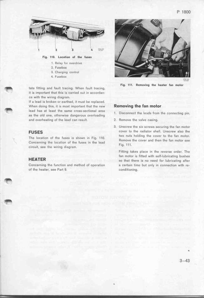
Fig. 11O. Loc8tion ot the t_ses
1. Relay for overdrive
2. Fusebo_
3. Charging control
4. Fusebo_ ,,o,,_vu,
Fig. 111. Removing the heatBr ta_ motor _
_ tate fitting and fault tracing. When fault tracing,
it is important that thís is carríed out in accordan-
ce with the wiring diagram.
If a lead is broken or earthed, it must be repIaced.
_ When doing ihis, ii is mosi imporiani ihai ihe new Removing the _an motor
Iead has at least the same cross-sectional area 1 . Disconnect the leads from the connecting pin.
aS the OId One, otherWISe dangefouS oVerloadlng
and overheating of the lead can result. 2. Remove the valve casing.
3. Unscrew the si_ screws securing the fan motor
Fu_E_ cover to the radiator she__. Unscrew afgo the
two nuts holding the cover to the fan motor
The _oCatjon of the FUSeS IS Shown _n F_g. 1 1 O. _ '
emOVe the COVer and then the fan mOtOr See
Concerning the _ocat_on of the fuses _n the Iead
c._rcu._t, gee t__e w._r._ng d.,agram. FI9_ 1 1 1_
Fitting takes place in the reverse order. __he
HEA_Eff fan motor is fitted with self-lubricating bushes
so ihai ihere ,s no need _o, _,b,_,c,i_,,g ,_i,,
Concerning the function and method of operation a certaìn time but only in connection with re-
of the heater, see Part 9. conditioning.
f,
I 3-43
_
|

